Tag Archives: frame

Making the Frame (part 1)

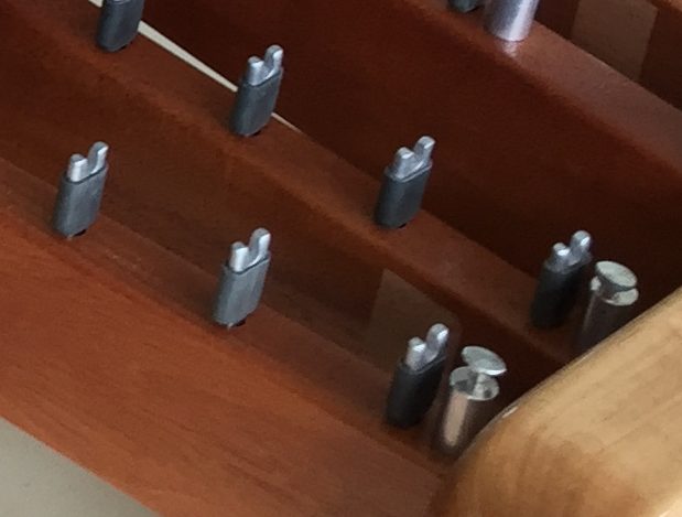
The first step in building the frame was to determine the total width between the two frame ends (i.e., the ID of the frame width). This was primarily dictated by the bar width and the gaps between the bars. As we’ve described, each of the bars was 1.5 inches wide. The width of the saddle pin with the surgical tubing attached was just about ¼ inch. We messed around a little and found that an extra 1/16 of an inch was about right to include for additional spacing around the pins, yielding a total gap between each pair of bars of 5/16 of an inch.

Next, we had to figure out how much space to leave  for the corner posts and springs that are situated between the end bars and the frame. We determined this spacing empirically by laying out the springs and the corner posts on a table top and adjusted the spacing until we had enough rough to comfortably reach the springs between the outside bar end and the inside edge of the frame end. We found that 3 cm was about right for this spacing.

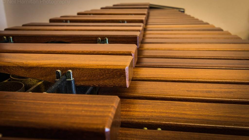
Now we had enough information to compute the total distance between the frame ends. For those of you who have gotten this far, I probably don’t have to tell you that xylophone bars are laid out like piano keys where the white natural keys are toward the player and the black accidental keys are toward the rear. But just to make it clear, here is a rough layout of my 44 bars:

Bars roughly laid out on a table top

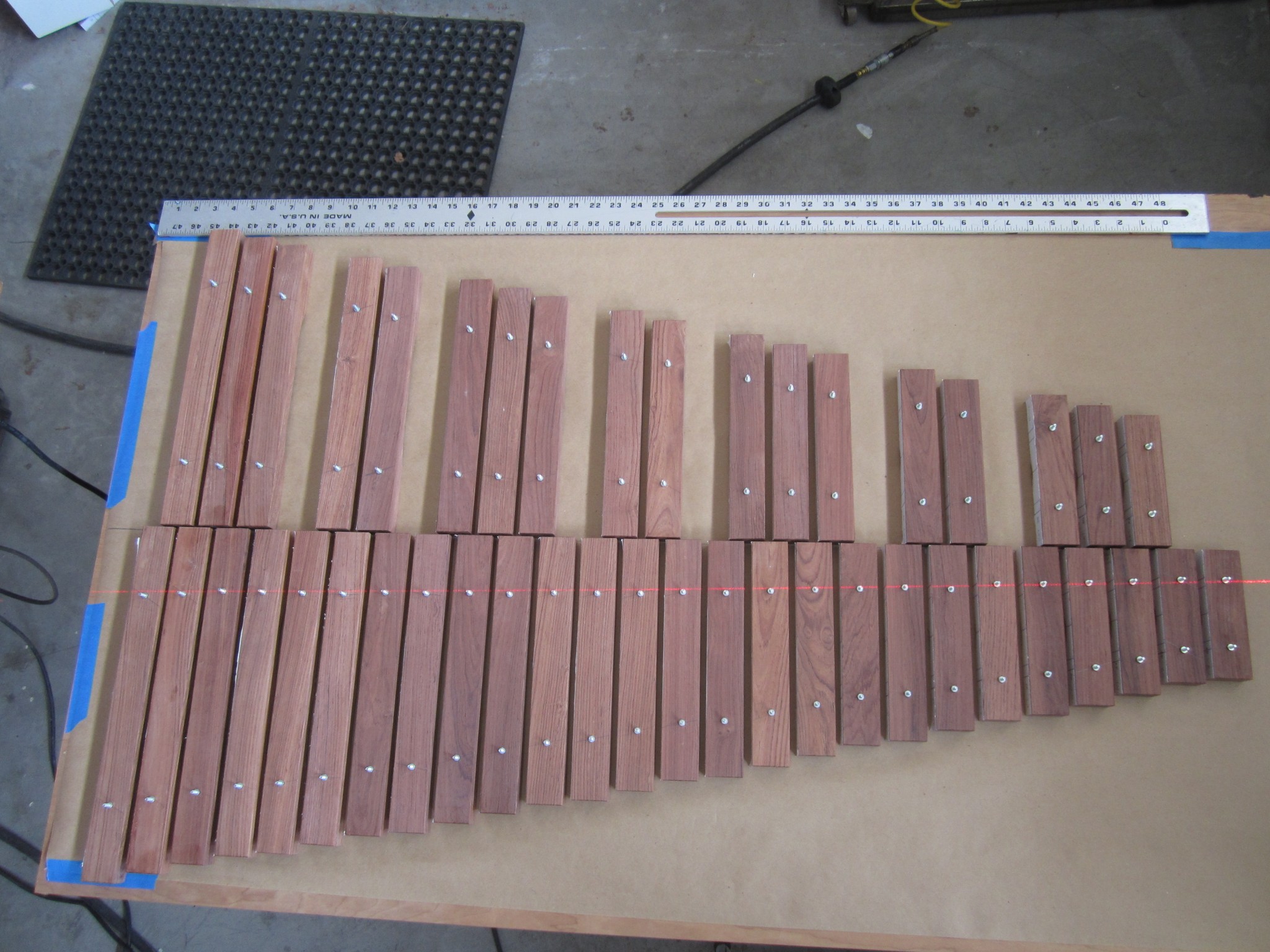
As you can see, the natural bars (at the bottom of the photo) determine the total width of the instrument, since the total width for these is greater than for the accidental bars. So the total inside dimension of the instrument is becomes

ID = (3 cm) + (26 bars)*(1.5 inches) + (25 gaps)*(5/16 inches) + (3 cm)
ID = 124.904 cm


The bar width and gap width define the X location (i.e. left/right) of each natural bar, and the pins are of course just centered between each bar. The X center position of each accidental bar just lines up with each natural bar gap center. I had a big complicated Excel spreadsheet that computed all of these dimensions, but this turned out to be more complicated than it needed to be, so I won’t confuse you by including it. I’m sure you can do a bit of arithmetic and determine the bar locations…

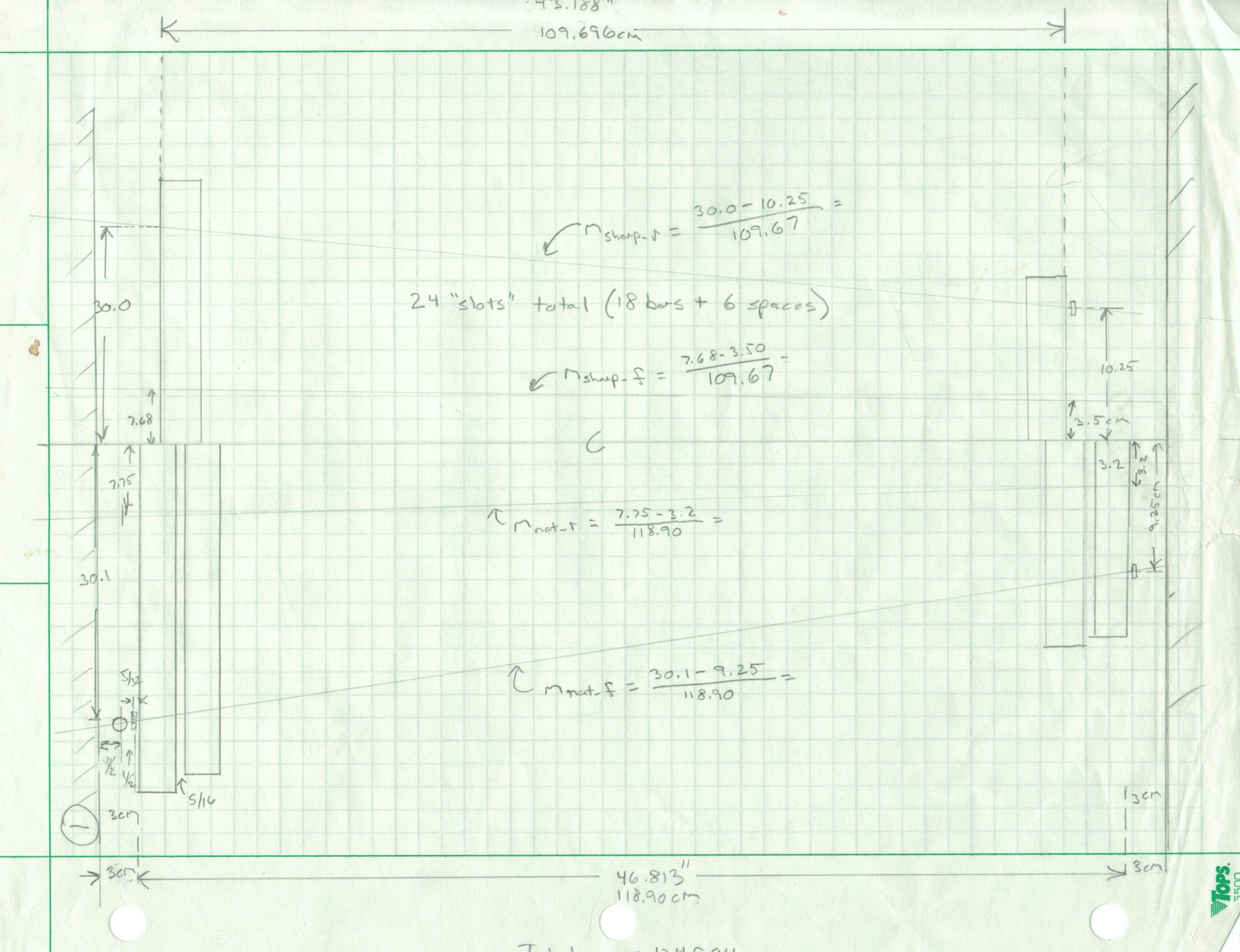
Dimensionally, we also had to determine the Y spacing (i.e., fore/aft) between the rails. Recall that the angles of the bar support rails was previously determined by lining up yellow thread suspended by posts with the average node locations. With the 124.9 cm ID spacing drawn on a large piece of construction paper, we simply marked the physical locations of the thread intersection with the inside edges of the frame ends on the paper for both the natural and accidental bars. We were careful to allow for clearance necessary to ensure that the aft ends of the natural bars were about ¼ inch away from the front accidental support rail. This established the center lines for each of the four angled support rails. Here are a couple of scrappy drawings that may help to illustrate all of this.

Drawing showing support rail layout
Drawing showing bar layout


In addition to the photo at the top of this page, here is another picture of the rails attached to the frame ends to illustrate the geometry:

IMG_0203
Frame showing elevated accidental support rails in the foreground


The only dimensioning left was to determine the Z spacing (i.e., up/down) of the accidental bars relative to the natural bars.  You can see in the photo above that the rails for the accidental bars are elevated above the natural bars. Elevating the accidental bars minimizes the fore/aft spacing of the natural and accidental bars by allowing the accidental bars to overlap the natural bars. The vertical gap between the natural and accidental bars was sent to ½ inch to ensure that the bars would not touch even if the string was loose and the bars sagged.

Laying Out the Frame Ends

We built the frame ends out of 8/4 maple (after dimensioning the lumber, the thickness was about 1.75 inches) that had a bit of figure to it. We wanted these to be beefy, because we knew that it needed to keep the support rails from racking, and it needed to support bolt-on legs. However, at this point we weren’t quite sure what exact shape we wanted for the frame ends but did know that we wanted the top of them to be roughly level with the top of the suspended accidental bars. So we oversized them prior to cutting the mortises that would receive the rail tenons. We had to figure in the total height of the bar above the suspension rail, which is of course a function of the saddle posts that hold up the bars. So we drew  the following picture to try to get all of the dimensions right. Again, this picture a pretty scrappy picture, but at least has all of the dimensions annotated.

Drawing showing elevation layout

When laying out the mortise locations for the Maple frame ends, we indexed everything from the top and fore/aft center of the rectangular frame end pieces. The rails themselves were made from 1×2.5 Mahogany stock. We chose Mahogany because it is dimensionally stable (i.e., unlikely to bow,) because we thought it would look good with the Maple and Rosewood and because we had it on hand. For strength, we wanted the largest tenons that we could reasonably make. The largest chisel for my tenoning jig is ½ inch, so that established the width of the tenons. To keep the shoulder consistent at ¼ inch, we made the tenons ½ x 2 inches.

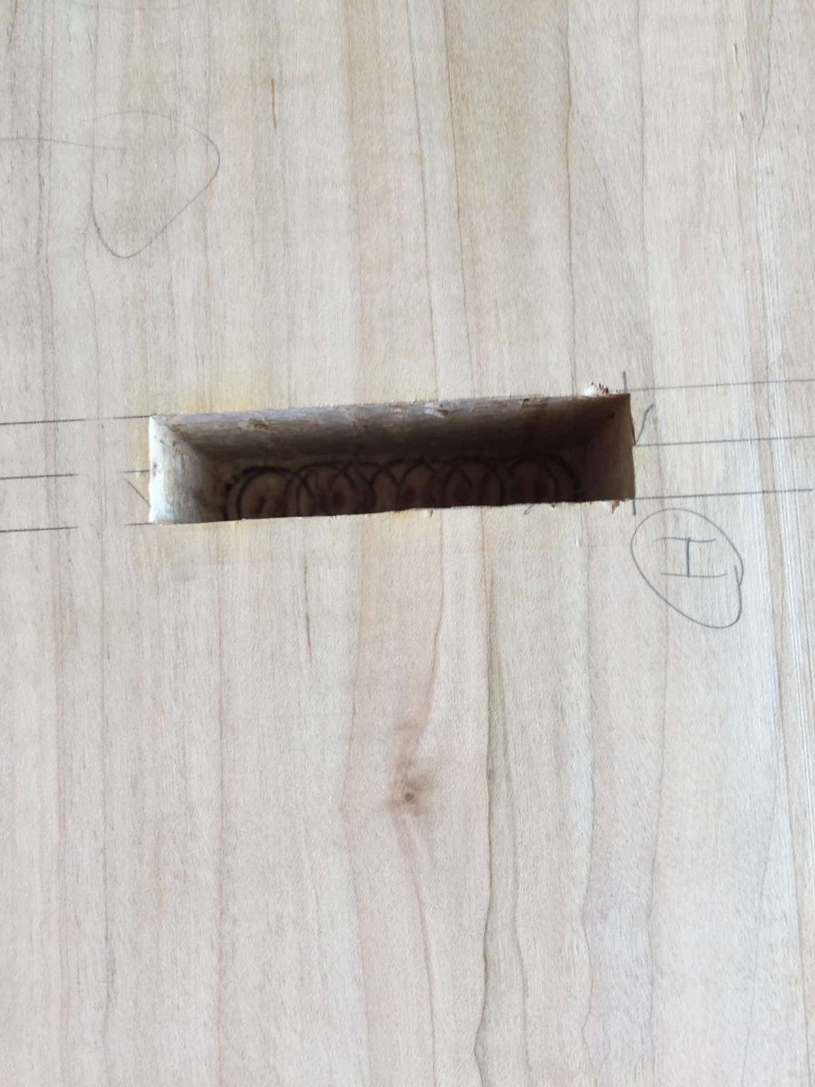
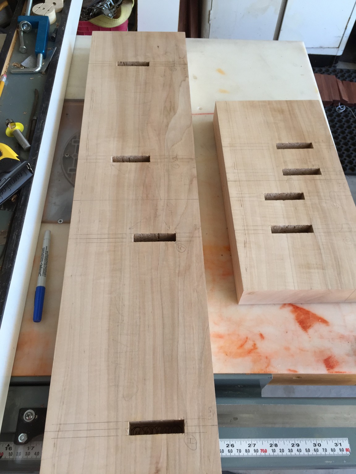
To keep the layout as simple as possible, we centered each of the support pins on the midpoint (in the thickness direction) of the Mahogany support rails, so the center line on these rails had to meet up with the marked locations on the frame ends accurately or the suspension strings wouldn’t pass through the center of the bar holes. So getting the mortises accurately placed in the Maple end frame pieces was important. Here is a few photos of the mortised frame ends:

The right frame end with mortises
Zoom of 2.5x1/2 inch mortise
Zoom of 2.5×1/2 inch mortise
Both Maple end frames with mortises

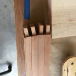
With the mortises cut, we had to make the tenons on the ends of the Mahogany support rails. What made this somewhat tricky was that these tenons had to be angled, relative tot he long axis of the rails. Angled tenons are always a bit tricky, but this was complicated by the fact that each of the four tenons for a given end were at different angles – a lot to keep track of.

I cut these angled tenons using a delta tenoning jig on my table saw, with Jack on quality control (i.e., making sure I got the correct angles and in the correct directions). I don’t have any photos of this, but I’m sure there is lots of info on the web that describe cutting angled tenons. Personally, I think the “cheek” cuts on the shoulders is the hardest part.

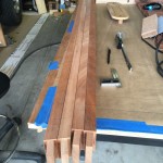
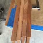
Here are a few photos of the final tenons:

Next up

The tenons and mortises were cut, but we still had to mark and drill all of the holes for the posts and had to shape the end frames. We’ll discuss that, and a few other odds and ends, in the next post.


Designing the Frame

The previous work that we had done to establish the suspension hole locations provided precise angles for the suspension rails. These angles, coupled with the bar lengths, established the fore/aft spacing of the natural and accidental bars. We decided to use 1 inch thick rails, so we had to just ensure that all of the aft ends of all of the natural bars had sufficient spacing from the front accidental support rail. We choose to leave 1/4 inch spacing between the natural bars and the support rail just to allow us a little wiggle room. Constructing the xylophone frame, including the rails that support the bars and the two end pieces, was pretty straight-forward woodworking, but we had to put some thought into the suspension posts and how the resonator tubes would be mounted.

Here are some practical matters that had to be addressed that might affect the frame design and therefore had to be addressed first:

  1. What to use for the posts that support the suspension strings?
  2. The diameter of the resonator tubes?
  3. How to support the resonator tubes?

The question of posts was important, because, depending on the thickness, it might have a bearing on the bar spacing. The post height might also affect the frame design, so we needed to figure that what our posts were going to be before building the frame.

There was a similar issue for the resonator tubes – the diameter might drive the spacing of the frame. Although this seemed like less of a concern than the post selection, I had learned from my previous woodworking projects that you always select hardware first (e.g., it is easier to build a box around available hinges than to find hinges that fit a project you’ve already built). So it seemed smart to figure out what material was available and cost effective.

I wasn’t as concerned about the last question, how to mount the tubes, but it seemed like giving this some thought could keep me out of trouble down the road.

The Posts

I anguished over what to use for posts. Most commercial xylophones that I found had posts like the ones shown in the image at the top of this page. I saw a few variations, like posts with a through-hole rather than a “saddle” to support the string, but all of the posts were similar and were cut from flat metal. In addition to the post itself, most included a rubber sleeve to keep the bars from buzzing against the metal during play. I had found a source of replacement posts made for Musser-brand instruments here, but they’re about 90 cents which doesn’t sound bad until you realize that I need 108 for the instrument! I also needed the rubber sleeves, which were sold by the same vendor for about a buck a piece – ouch! So I wracked my brain trying to determine an easy way to build them. Dr Entwistle weighed in too, but every idea we came up with (e.g., brass bolts with a bit of machining) was either nearly as expensive or required a bunch of per-post labor. Now I am pretty patient when it comes to repetitive tasks (hey, I built a xylophone, right!), but hand machining 108 posts was more than I could stomach.

So at the end of the day, I bit the bullet and just bought the posts from the link above. I also bought some springs that tension the suspension strings and some really nice end posts that support the tension load of the strings at the corners. It was hard to tell from the photos on the vendor website, but when I got these I was actually pretty pleased with the quality. Here are a couple of photos of the “saddle posts” and the corner posts:

Musser "saddle" posts
Musser “saddle” posts
Musser corner posts
Musser corner posts


The springs were nothing special, but were inexpensive, so I went ahead and bought them from the same site. Here was an invoice of the parts:

Invoice for post hardware

Actually, you will notice that I messed up and only ordered 100 posts – argh! I ended up ordering another 10 from a different vendor that had cheaper shipping for small orders.

The only thing left was the rubber bumper material – I wasn’t so keen on giving Musser another hundred bucks for a bunch of little rubber pieces. I had some surgical tubing around for another project, and I found that with a little soapy water for lubrication, I could slide it over the posts for a perfect fit. The only downside was that it was that standard tan color that is typical of surgical tubing. However, I found some black tubing of the same size from this source. This was only $10.95 (with free shipping) for 10 feet, which was more than enough. Sweet, that’s about a $100 savings! It looks great on the post too. Check this blow up of the posts with the surgical tubing and the corner posts.

Zoomed image of my posts with the rubber jacket

Resonator Tube Material Selection

We really, really, really wanted to make the resonator tubes out of brass. Polished brass just looks so classy, and we were trying to make an instrument that looked as good as it sounded. However, the cheapest price I could find for brass was about $13 per foot. Considering that we needed about 20 feet (more about the resonator tube lengths in a later post,) that was a pretty expensive option. We also considered that brass is pretty heavy, so the supports would have to be beefy enough to support the weight. At the end of the day, we compromised and decided to make the tubes out of aluminum – not quite as sexy as brass, but after applying a brushed finish and some lacquer, they looked pretty good.

We just had to figure out the diameter. Our rosewood bars are 1.5 inches wide, and we planned to space them about 1/4 apart. So the tubes could be up to 1.75 inches in diameter. However, the paper by Bork (cited on a previous post) suggested that resonator “cross-talk” with neighboring notes could be an issue if the bars were too close together. This potential issue would be worse for the B-C and E-F bars, which are only a semitone apart and adjacent. However, we also considered that a diameter of 1.75 inches would be convenient from a mounting standpoint, because the bars would be butted together, which might ease assembly and aesthetics.

In the end, the solution was driven by the available materials; after a local supplier gave me a quote of $350 for 20 ft of aluminum tubing (!!), I started looking online. Ultimately, I bought 1.5 inch tubing with 1/16 walls. This was about $15 per 4 foot length from Speedy Metals, which is a very reasonable price. (In general Speedy Metals is a great vendor with lots of selection and prices – I love this place!) I calculated that I needed 5 pieces, but bought 6 just in case. Speedy Metals also had 1.75 inch tubing, but only in 1/8 inch wall, which was a lot more expensive and overkill for this application.

Mounting the Resonator Tubes

All of the xylophones that I saw connected the tubes together to form an assembly and then hung them in some fashion from the frame ends. I decided to attach wood cleats to the frame ends to support the resonator tube assemblies. You’ll see more of this in a later post, but I used 1×1/8 aluminum flat stock to tie all of the tubes together. The aluminum is 6061, which is pretty stiff, but bendable; this was important because I had to bend the these support rails at the end where the wood support rails converged.

Here is a snapshot of the invoice for all of the aluminum:

Invoice for resonator tube material

Next Up

Chronologically, the next step that Jack and I performed on the xylophone was the construction of the resonator tubes. However, that included a bit more research and math, so to mix things up a little I will discuss the frame construction in the next post. Finally a little wood working!