Tag Archives: construction

Making the Frame (part 2)

After cutting the tenons and mortises, Jack and I did the standard fine tuning on the mortises to get the parts to fit together accurately, but without a bunch of man-handling. It was important that the mortise and tenon fit wasn’t too tight, because four joints on each end must be fit simultaneously during the glue-up, and it is very hard to seat them all if they are tight. After a few dry fits, we were ready to mark and drill the holes in the rails that receive the saddle and corner posts.

Post Holes

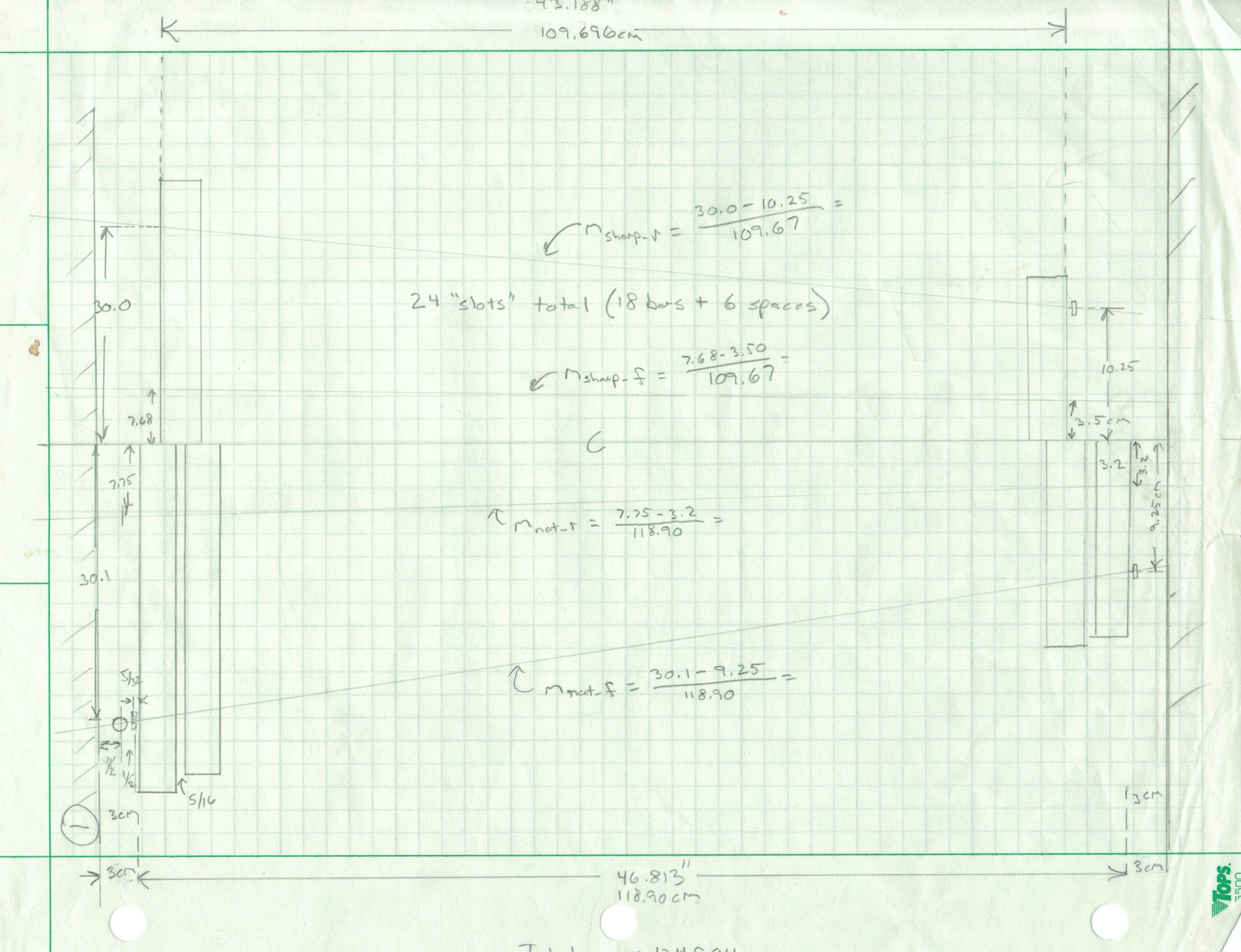
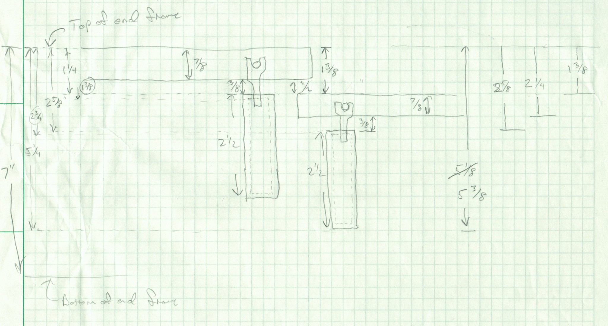
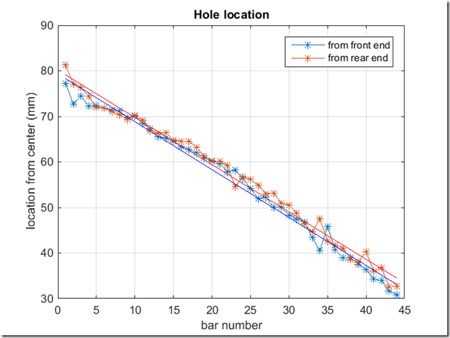
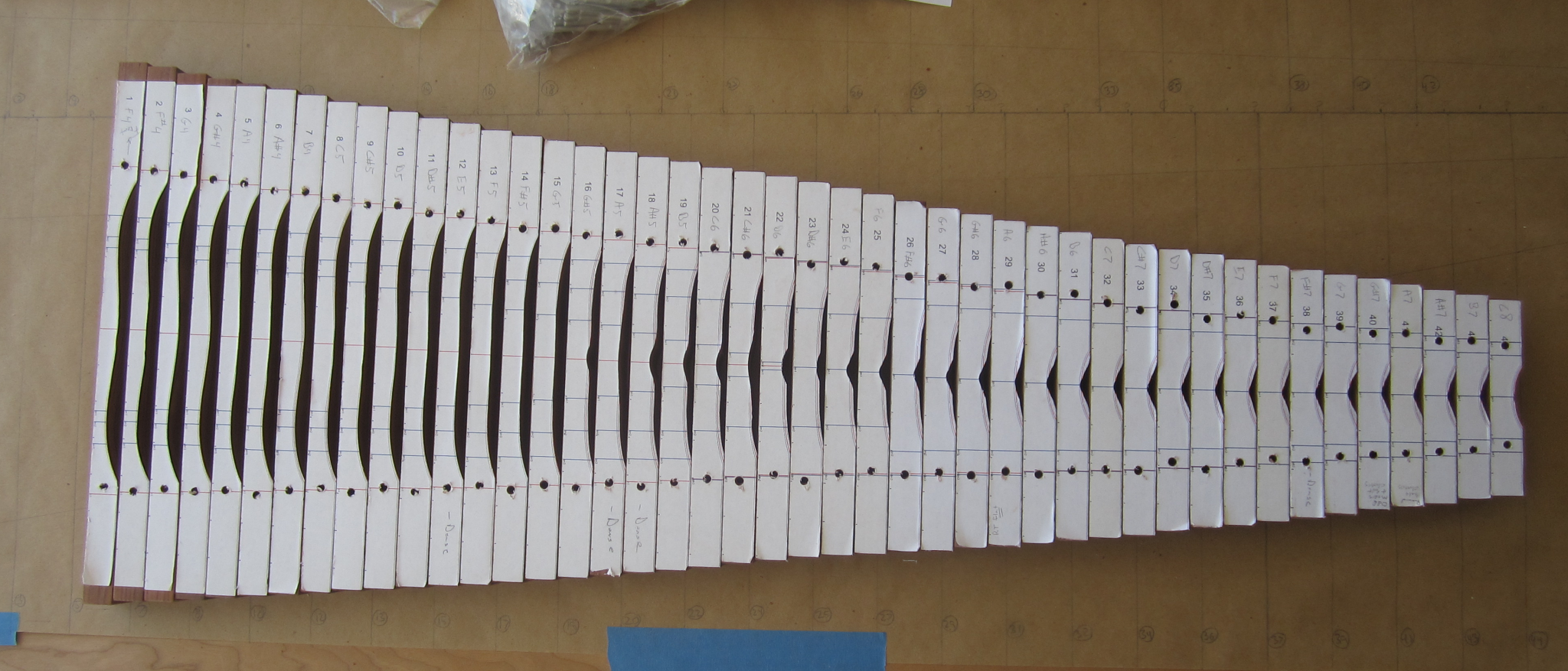
Now I’m not going to lie – I can tend to be a bit anal-retentive when it comes to woodworking. Feeding this natural tendency was the fact that I knew that accurate placement of the posts was critical to avoid pinching the bars between the posts. To determine the hole locations, I created an Excel spreadsheet that computed the location of each post on each of the four rails. The computed locations were distances down the length of each rail, relative the shoulder of the tenon. The only problem is that I kept screwing this up- mostly due to the four unique angles and all of the offsets involved. I would compute the locations and then mark them  on the rails with jack reading off the dimensions. But when we checked them, there would be some systematic error – like I hadn’t accounted for the offset due to the pin being in the center of the rail. I think we did this three times before we got it right – argh! Both Jack and I were frustrated by this tedious process (did I mention that there were 108 holes?!)

After we did it this way, I realized that there is a much simpler approach that I would use if I ever did this again. Let me explain…

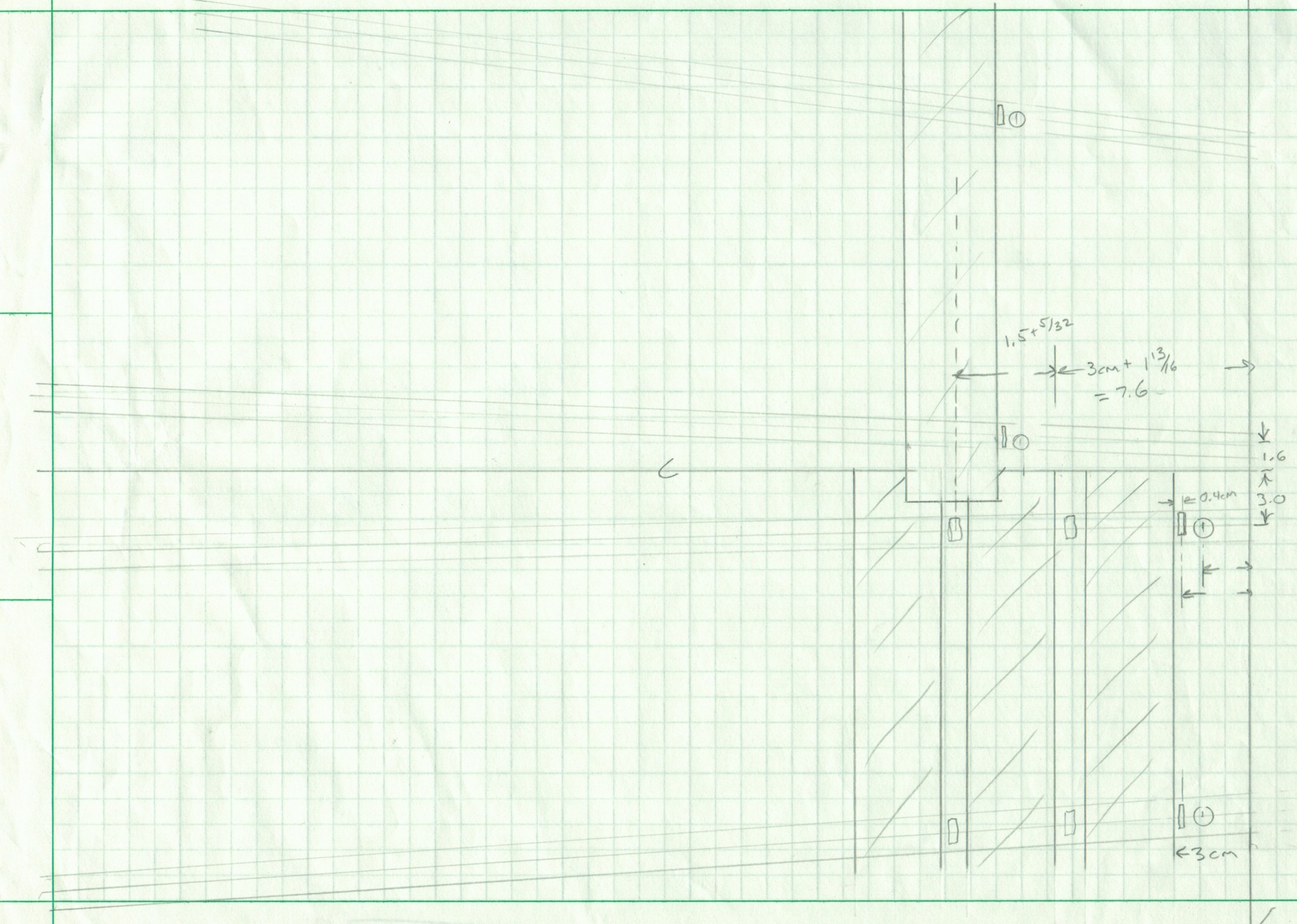
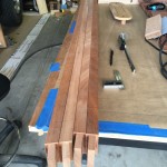
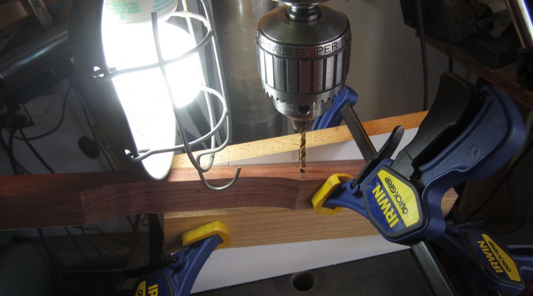
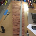
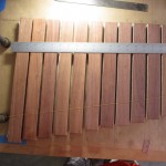
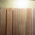
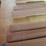
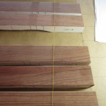
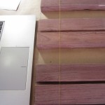
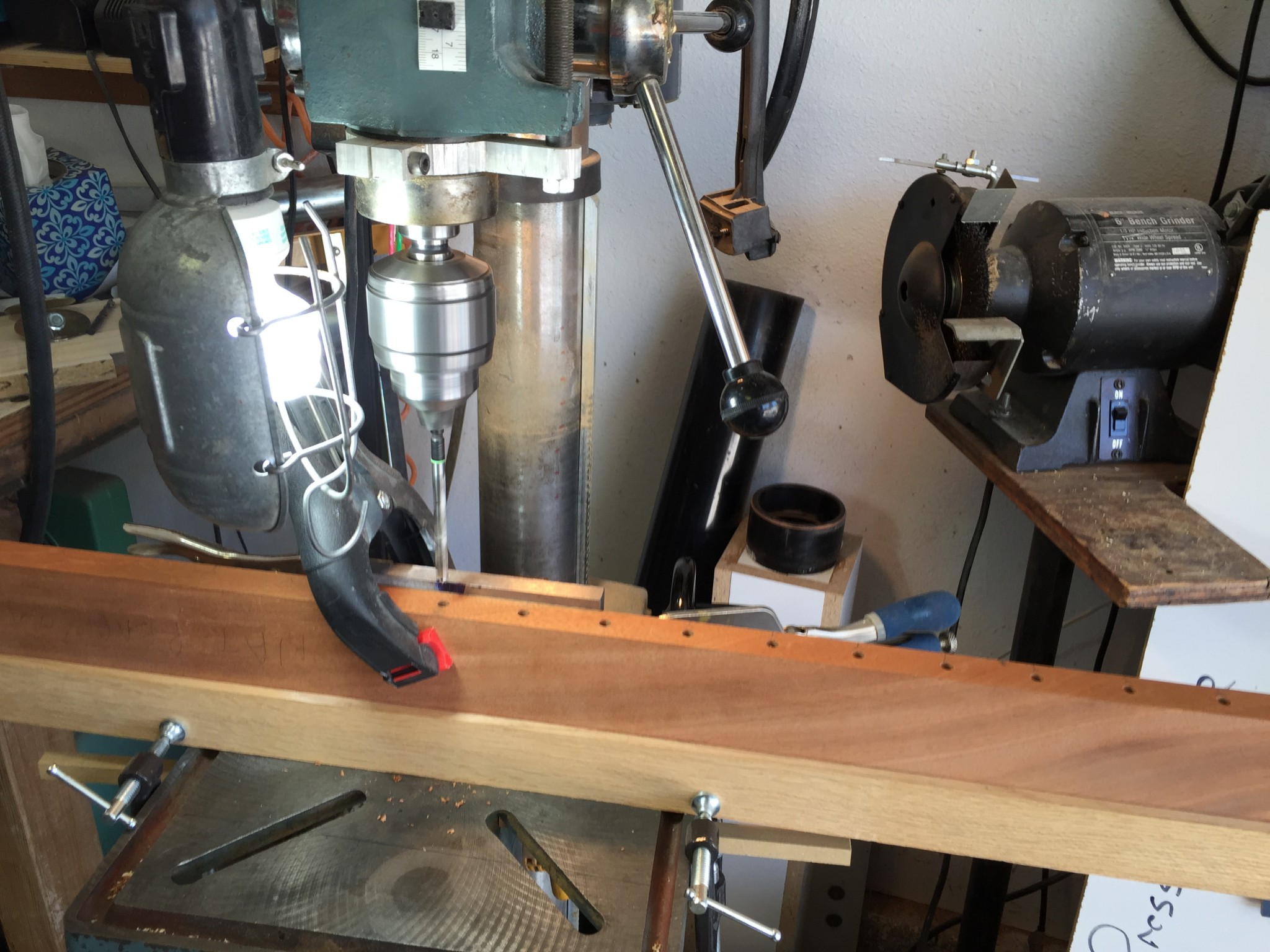
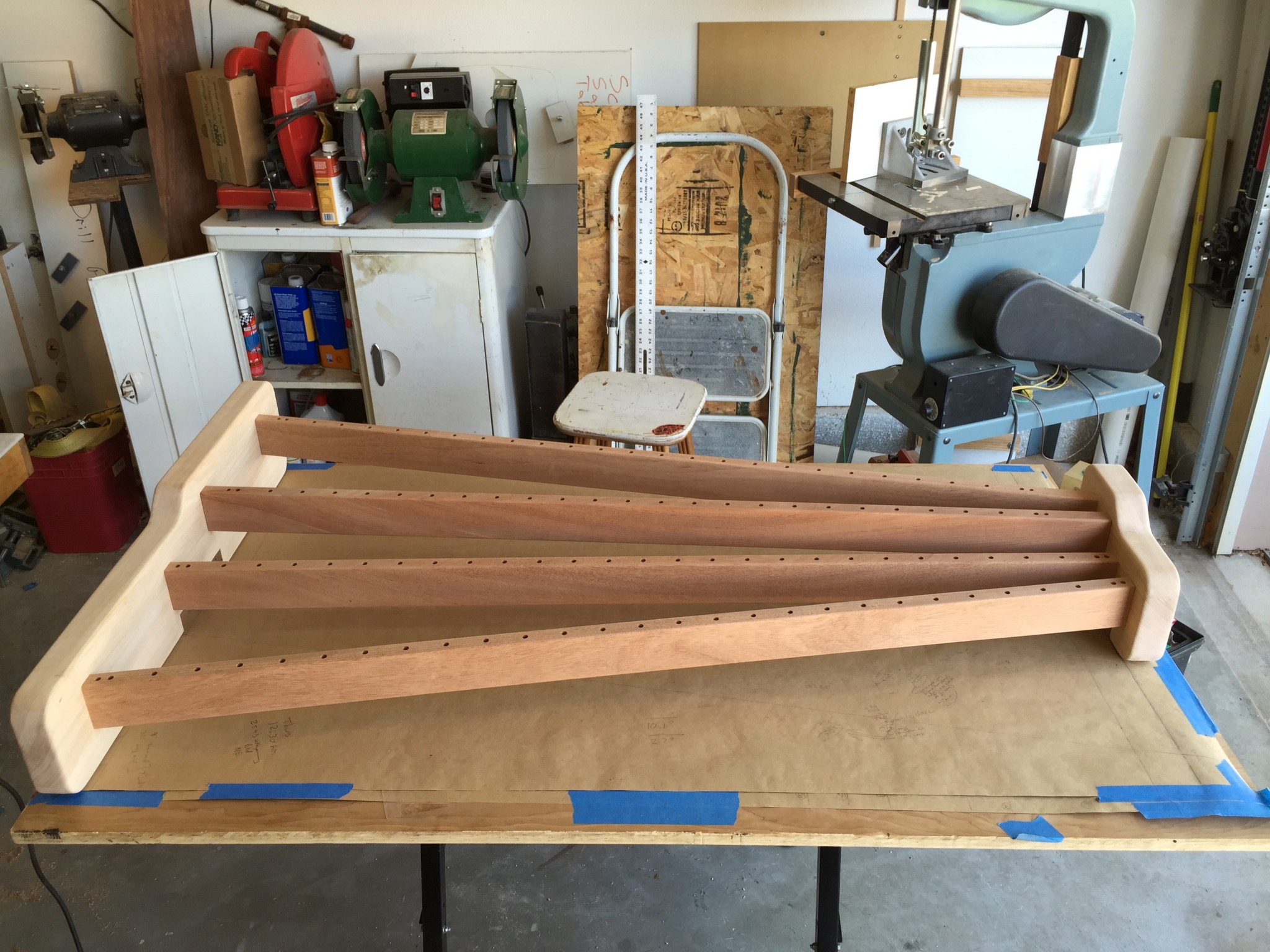
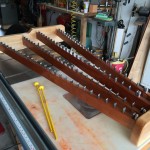
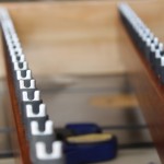
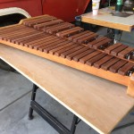
Computing the post locations relative to the left ID of the frame is straightforward (as opposed to distance down the rail). It is really just accounting for each bar and gap width. You do have to be a little careful with the offsets (i.e., edge-to-corner post, edge to first saddle pin, etc), but it is do-able with a little care. The tricky part is the angles involved and the fact that the index mark for the hole location has to be at the edge of the rail to make the drilling operation efficient. Let me clarify. Check out the photo at the top of this post. This is the setup on my drill press where we drilled the holes. Here is a zoom of the center of that photo:

Blowup of drilling operation showing the index marks

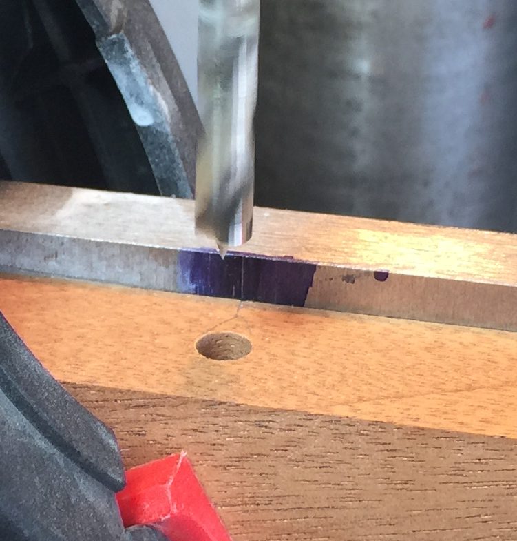
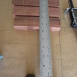
It may be hard to see in the photo, but there is a thin pencil mark on the edge of the Mahogany support rail that must be aligned with the scribed line on the steel angle jig behind the rail. The drilling process for each hole was basically to align the marks, apply a spring clamp to hold the board against the steel fence, and drill the hole. The spacing between the drill bit center and the steel fence was exactly 1/2 inch so that each hole would be precisely centered on the width of the board.

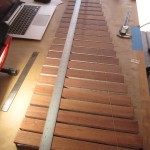
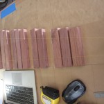
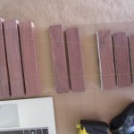
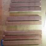
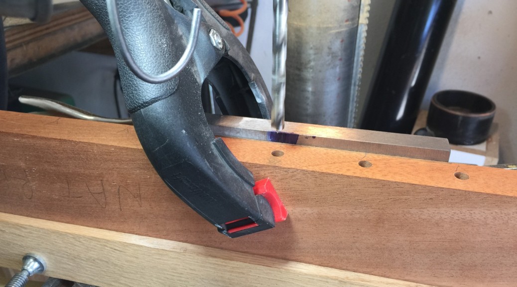
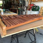
Here is a wider field of view photo of the drilling setup that may help:

Drilling setup
Drilling setup

Because each rail is angled, there is a small offset between the desired X location of each hole and the mark at the edge of the board. Neglecting this, or getting the offset in the wrong direction is how I kept screwing up. Also, when making the marks on each rail, it is easy to mess up, since the distance down the rail is relative to the rail center line, not the edge. This is another way I screwed up. So here is a much easier approach that occurred to me after the fact.

Rather than trying to account for this angle-dependent offset, I would do the following:

  1. Dry fit the frame together
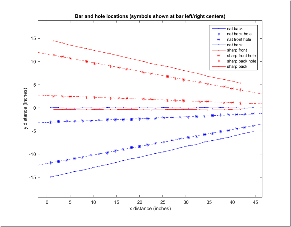
  2. Compute the location of each hole relative to the left or right ID of the frame end piece (i.e., in the X direction)
  3. Using the protractor head on a combination square, set the angle so head is against the rail and the blade is aligned with the frame end (so the blade is parallel to the Y axis)
  4. Slide the combo square down the rail to align the blade with the desired X location (e.g., using a tape measure that measures distances form the frame end ID) computed for a given hole.
  5. Draw a line on the top of the rail. This line will be slanted relative to the rail perpendicular.

Now you will have a slanted pencil mark at each post location. When aligning the mark on the drill press, you can not just line up the pencil mark with the index line on the steel angle block. If you do this, the hole will be offset a bit from the desired location due to the 1/2 inch thickness of the rail and the fact that the line is slanted. Rather, you will have to align the drill press index mark with the intersection point of the slanted line and the mid-point of the rail. A small right angle block could facilitate this, or you could draw an additional perpendicular line at each mark location.

Hopefully, my lesson will save you some pain, or perhaps you will have better luck with the calculations and getting all of the angles right – we finally did, but it was painful.

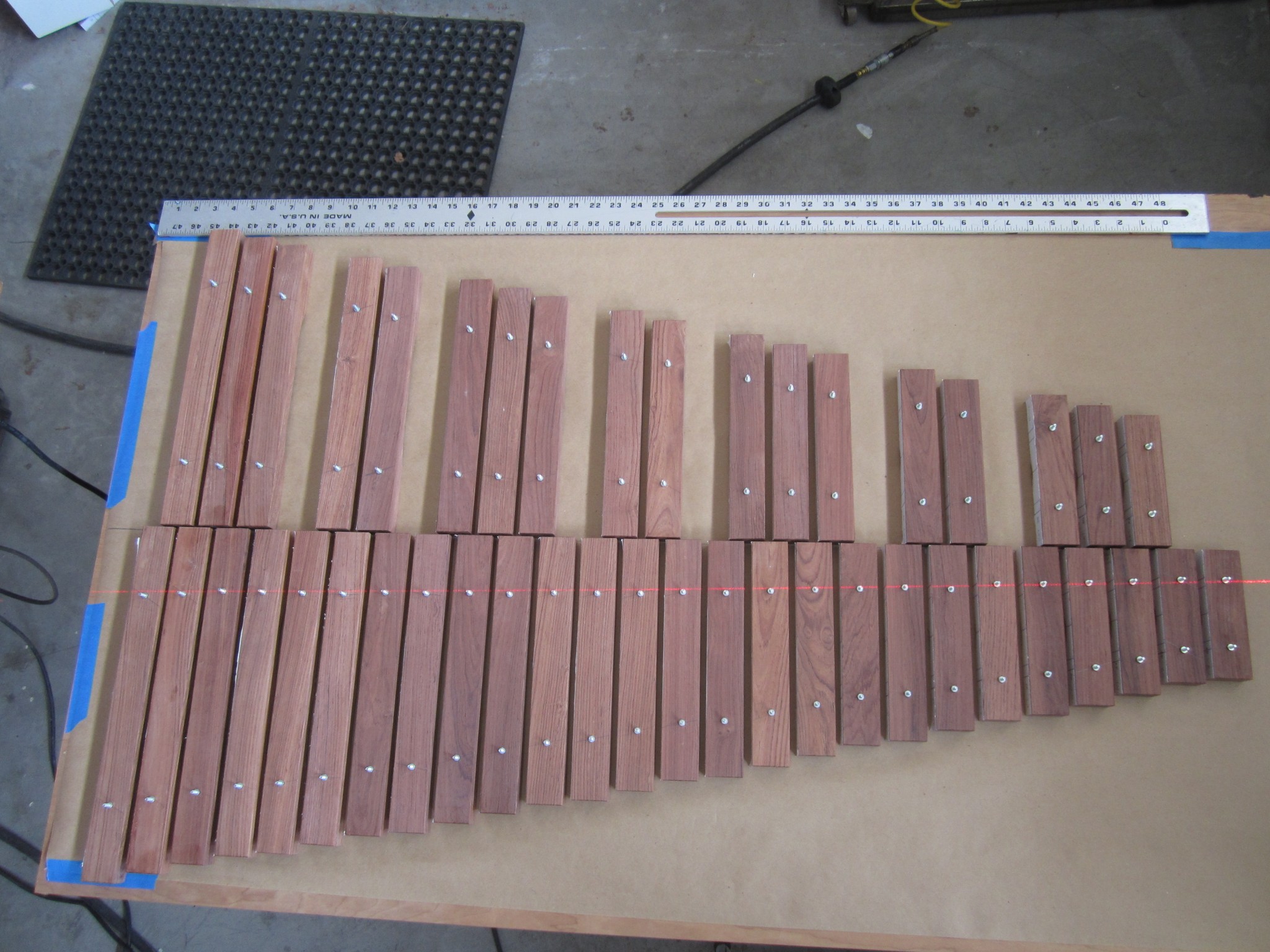
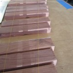
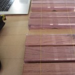
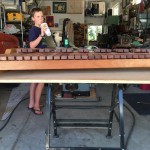
In the end, we got all of holes drilled, temporarily pushed all of the posts in the holes, and temporarily strung the bars with some string. Here is a photo of Jack with our assembled unit. It’s starting to look like a real instrument.

Jack, proud of our handiwork

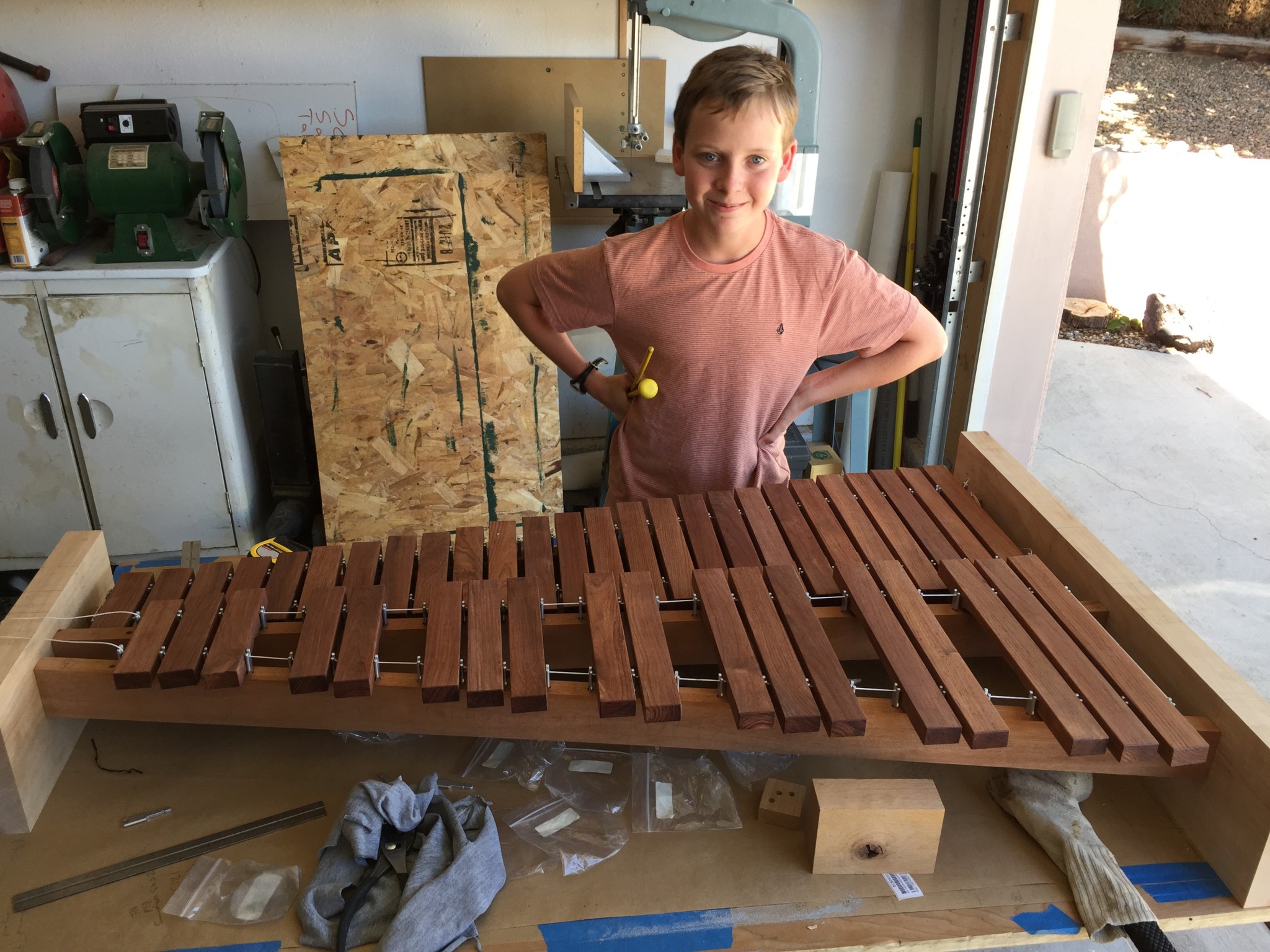
Jack couldn’t resist playing a little ditty. Here is a video of Jack playing his evolving xylophone for the very first time:

Shaping the Ends Pieces

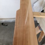
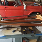
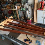
As shown on the photos of the previous posts, the frame ends at this point were just rectangular blocks, which look pretty clunky. As previously noted, we placed the mortises so that the top of the accidental bars were at the same elevation as the top of the rectangular frame ends. This was just an aesthetic decision. We thought it would look good to extend this idea to the natural bars too, which required the frame ends to “step down” to the elevation of the natural bar tops.

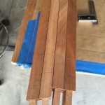
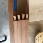
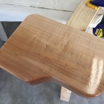
To avoid square, sharp corners, we also added little ramps that connected the two elevations and rounded all of the corners. Here is a photo of the nearly finished end pieces.

Nearly finished end pieces.

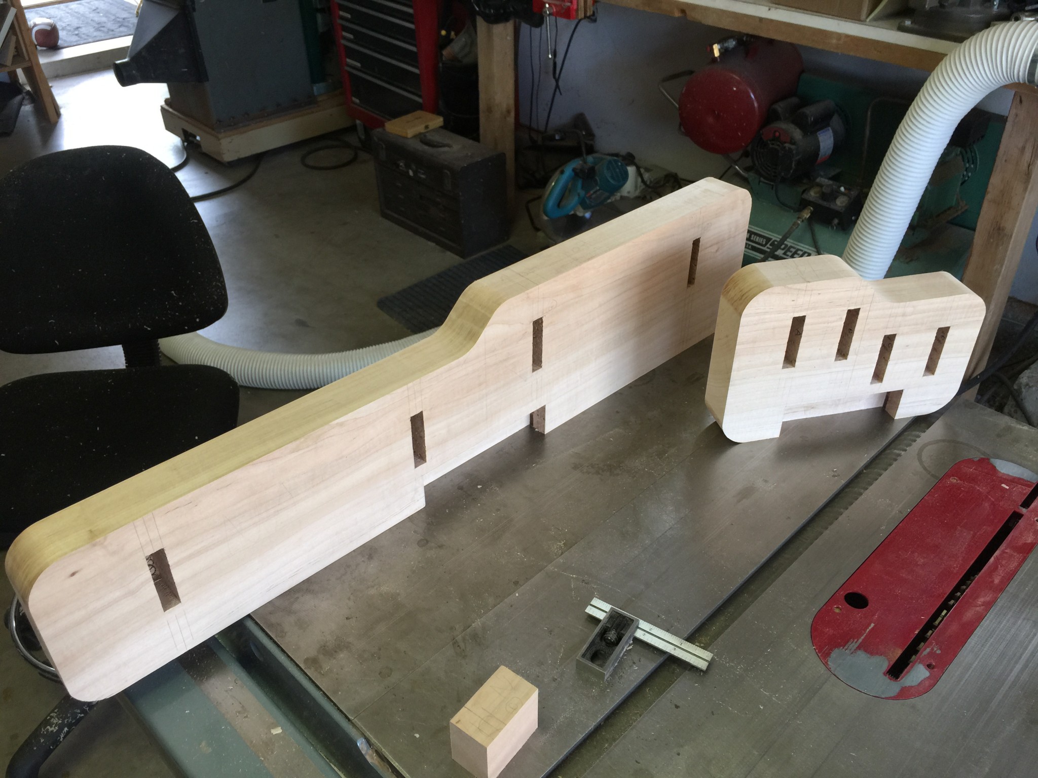
Notice that we also cut some big, rectangular mortises in the bottom of each end piece. This is to accept the two legs that we had yet to build. We’ll write more about the leg and foot construction in a later post.

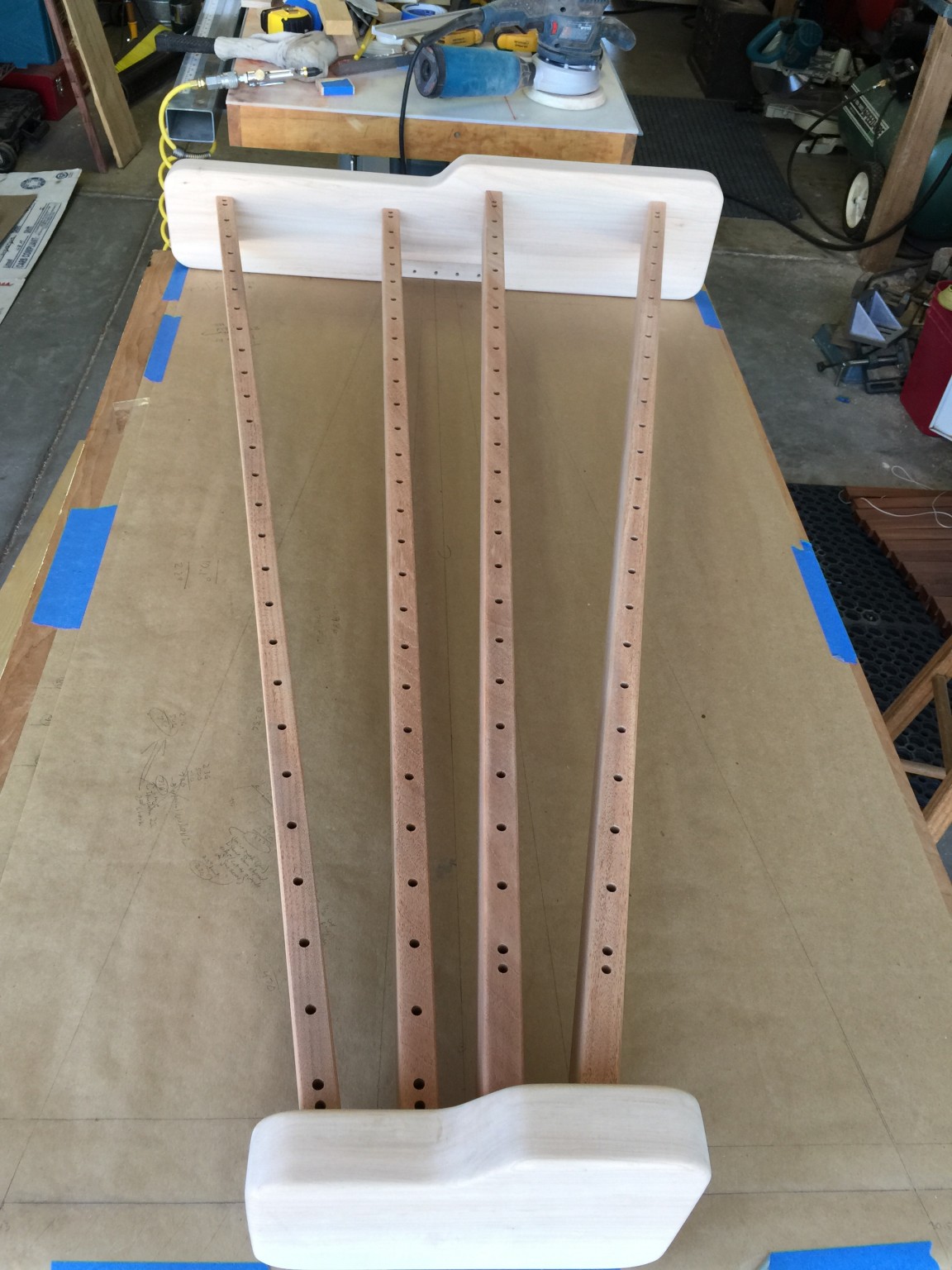
To smooth the sharp corners, we routed a 1/4 round-over on all of the edges and dry-fit the whole thing together to take a look. Here is the result:

Completed frame (without finish)

 Applying Finish

I chose lacquer for the frame finish. I like lacquer because it really brings out the depth in the wood but also because it drys quickly, so it is fast to build up a finish. We decided to finish the rails and end pieces prior to assembly for a few reasons. First, down at the right end of the instrument, the spacing is a little tight, so it is hard to spray finish in there. Second, there is inevitably glue squeeze out at the joints, and it is often hard to remove all of that glue prior to finishing. Any glue left behind will keep the wood from absorbing the finish which leaves unsightly “splotches.” So we put blue painters tape over the mortises and tenons and sprayed the parts with an HVLP gun. (I use a cheap $100 HVLP system from Rocker for the finish. For the price, this thing is actually pretty decent.) Here are a few photos:

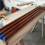
It’s always fun to watch the grain pop on wood when lacquer is applied. The finish also brought out the beautiful color of the Mahogany.

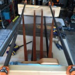
After the finish dried, we glued and clamped the frame assembly. This was a bit “butt puckering” because it is a tricky to get the tenons simultaneously inserted in to the mortises before the glue dries, especially in arid New Mexico where the humidity is so low. Here are few photos of the glue-up:

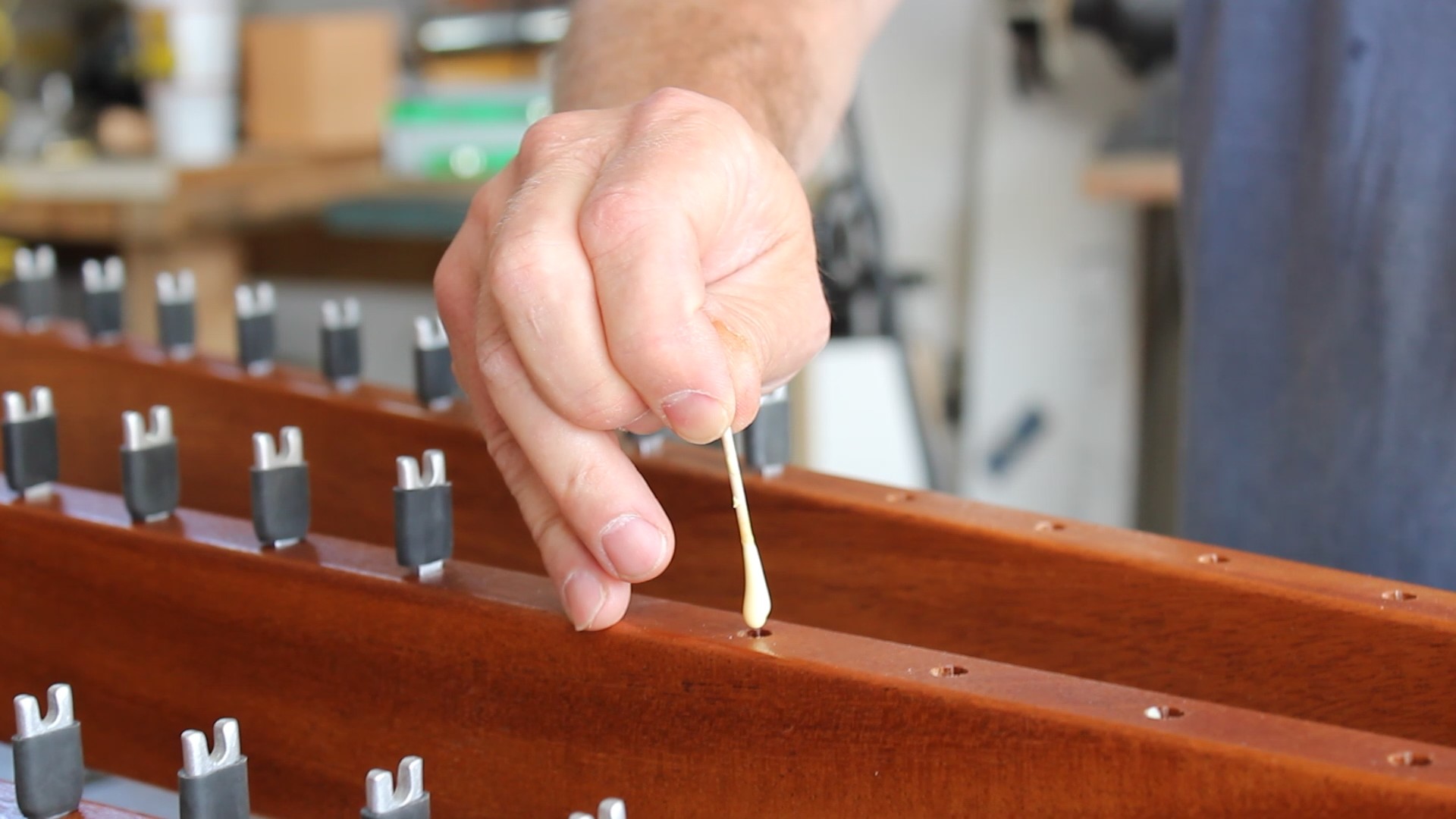
All that was left was to glue the posts into the rails. Each of the post holes was drilled with a brad-point bit to a fixed depth. This gave a nice square bottom to each hole that ensured that all of the pins would have the same elevation. The pins were snug in the hole, but over time may have wiggled out, or at least rotated, so I decided to drop a bit of glue in the bottom of each hole to lock the pin into place. I carefully inserted the glue into each hole using a toothpick and letting the glue drip in. This was slow going (did I mention that there are 108 holes,) so it took a while.  Here is a photo:

Dripping glue into post hole

Here are a couple of photos of the completed frame:

And then came the moment of truth – Jack and I strung the xylophone bars on some brown para-cord, attached the springs, and hung the bars. Pretty cool – we now had a fully functional instrument, minus legs and resonator tubes. Here are some photos of the finished product:

It had been a long time coming, but we finally had an instrument! Jack and I moved this up to his bedroom at this point, so he could mess around with it, and to get it out of the garage so we could start working on the resonator tubes. More on that in the next post.

We’ll leave you with Jack playing a little song in his bedroom.


Making the Frame (part 1)

The first step in building the frame was to determine the total width between the two frame ends (i.e., the ID of the frame width). This was primarily dictated by the bar width and the gaps between the bars. As we’ve described, each of the bars was 1.5 inches wide. The width of the saddle pin with the surgical tubing attached was just about ¼ inch. We messed around a little and found that an extra 1/16 of an inch was about right to include for additional spacing around the pins, yielding a total gap between each pair of bars of 5/16 of an inch.

Next, we had to figure out how much space to leave  for the corner posts and springs that are situated between the end bars and the frame. We determined this spacing empirically by laying out the springs and the corner posts on a table top and adjusted the spacing until we had enough rough to comfortably reach the springs between the outside bar end and the inside edge of the frame end. We found that 3 cm was about right for this spacing.

Now we had enough information to compute the total distance between the frame ends. For those of you who have gotten this far, I probably don’t have to tell you that xylophone bars are laid out like piano keys where the white natural keys are toward the player and the black accidental keys are toward the rear. But just to make it clear, here is a rough layout of my 44 bars:

Bars roughly laid out on a table top

As you can see, the natural bars (at the bottom of the photo) determine the total width of the instrument, since the total width for these is greater than for the accidental bars. So the total inside dimension of the instrument is becomes

ID = (3 cm) + (26 bars)*(1.5 inches) + (25 gaps)*(5/16 inches) + (3 cm)
ID = 124.904 cm


The bar width and gap width define the X location (i.e. left/right) of each natural bar, and the pins are of course just centered between each bar. The X center position of each accidental bar just lines up with each natural bar gap center. I had a big complicated Excel spreadsheet that computed all of these dimensions, but this turned out to be more complicated than it needed to be, so I won’t confuse you by including it. I’m sure you can do a bit of arithmetic and determine the bar locations…

Dimensionally, we also had to determine the Y spacing (i.e., fore/aft) between the rails. Recall that the angles of the bar support rails was previously determined by lining up yellow thread suspended by posts with the average node locations. With the 124.9 cm ID spacing drawn on a large piece of construction paper, we simply marked the physical locations of the thread intersection with the inside edges of the frame ends on the paper for both the natural and accidental bars. We were careful to allow for clearance necessary to ensure that the aft ends of the natural bars were about ¼ inch away from the front accidental support rail. This established the center lines for each of the four angled support rails. Here are a couple of scrappy drawings that may help to illustrate all of this.

Drawing showing support rail layout
Drawing showing bar layout


In addition to the photo at the top of this page, here is another picture of the rails attached to the frame ends to illustrate the geometry:

IMG_0203
Frame showing elevated accidental support rails in the foreground


The only dimensioning left was to determine the Z spacing (i.e., up/down) of the accidental bars relative to the natural bars.  You can see in the photo above that the rails for the accidental bars are elevated above the natural bars. Elevating the accidental bars minimizes the fore/aft spacing of the natural and accidental bars by allowing the accidental bars to overlap the natural bars. The vertical gap between the natural and accidental bars was sent to ½ inch to ensure that the bars would not touch even if the string was loose and the bars sagged.

Laying Out the Frame Ends

We built the frame ends out of 8/4 maple (after dimensioning the lumber, the thickness was about 1.75 inches) that had a bit of figure to it. We wanted these to be beefy, because we knew that it needed to keep the support rails from racking, and it needed to support bolt-on legs. However, at this point we weren’t quite sure what exact shape we wanted for the frame ends but did know that we wanted the top of them to be roughly level with the top of the suspended accidental bars. So we oversized them prior to cutting the mortises that would receive the rail tenons. We had to figure in the total height of the bar above the suspension rail, which is of course a function of the saddle posts that hold up the bars. So we drew  the following picture to try to get all of the dimensions right. Again, this picture a pretty scrappy picture, but at least has all of the dimensions annotated.

Drawing showing elevation layout

When laying out the mortise locations for the Maple frame ends, we indexed everything from the top and fore/aft center of the rectangular frame end pieces. The rails themselves were made from 1×2.5 Mahogany stock. We chose Mahogany because it is dimensionally stable (i.e., unlikely to bow,) because we thought it would look good with the Maple and Rosewood and because we had it on hand. For strength, we wanted the largest tenons that we could reasonably make. The largest chisel for my tenoning jig is ½ inch, so that established the width of the tenons. To keep the shoulder consistent at ¼ inch, we made the tenons ½ x 2 inches.

To keep the layout as simple as possible, we centered each of the support pins on the midpoint (in the thickness direction) of the Mahogany support rails, so the center line on these rails had to meet up with the marked locations on the frame ends accurately or the suspension strings wouldn’t pass through the center of the bar holes. So getting the mortises accurately placed in the Maple end frame pieces was important. Here is a few photos of the mortised frame ends:

The right frame end with mortises
Zoom of 2.5x1/2 inch mortise
Zoom of 2.5×1/2 inch mortise
Both Maple end frames with mortises

With the mortises cut, we had to make the tenons on the ends of the Mahogany support rails. What made this somewhat tricky was that these tenons had to be angled, relative tot he long axis of the rails. Angled tenons are always a bit tricky, but this was complicated by the fact that each of the four tenons for a given end were at different angles – a lot to keep track of.

I cut these angled tenons using a delta tenoning jig on my table saw, with Jack on quality control (i.e., making sure I got the correct angles and in the correct directions). I don’t have any photos of this, but I’m sure there is lots of info on the web that describe cutting angled tenons. Personally, I think the “cheek” cuts on the shoulders is the hardest part.

Here are a few photos of the final tenons:

Next up

The tenons and mortises were cut, but we still had to mark and drill all of the holes for the posts and had to shape the end frames. We’ll discuss that, and a few other odds and ends, in the next post.


Drilling the Holes

The last lengthily post described the method and results for the rough tuning of our 44 bars and described a few challenges that we encountered along the way. Here we are going to describe the process of determining the suspension hole locations and the actual drilling.

To simplify construction of the xylophone, it would be best to have the cord that suspends the bars follow a straight line; this allows straight support rails and straightforward placement of the suspension posts. Also, all of the commercial instruments that we inspected were built with straight suspension cords.

Having measured all of the node locations using the salt method, we were able to assess how linear the node locations were and how much they would deviate from a straight line. The next plot shows these results.

Hole locations with linear trend lines

The symbols are the measured node locations from the front and rear ends of each bar (we define “front” to be the bar ends that face the player). There is clearly a gentle deviation from linear, but it is modest, so I chose to ignore it. Doing otherwise would force me to mount the suspension posts along a curve, which would obviously complicate construction.

Of course, the holes must be drilled at an angle relative to the bars. To figure out the hole angles, I wrote a little code to plot the locations (as if you were looking down on the instrument). I left 1/4 inch spacing between the bars, which might be a little tight for mounting posts, but I can space them a bit more later if needed (this, of course, affects the angle slightly, but the change is negligible). The following figure shows the output of this code.

Bar and hole locations

There is a lot going in this figure, so let me explain. The plot basically shows the location of the bars’ ends and posts in physical space. The blue solid lines show the locations of the natural bar ends. The red lines give the same info, but for the sharp bars (also called the accidentals). As you can see, the front edge of the sharp bars overlaps the back end of the natural bars. This is allowed, as the rear bars are elevated. In general, it is desirable to have the accidental bars as far forward as possible to minimize the reach needed by the player. The asterisks show the measured node locations for each bar, and the dashed line is the best linear fit through the node locations. If you look carefully, you will note that the solid lines (the bar end locations) are a bit wiggly. This is because I shifted each bar for and aft (actually Matlab did it) to split the difference between the best-fit line and the node locations. I did this to minimize the distance between the linear fit and the true node locations. Aesthetically, this is somewhat undesirable (i.e., the bars ends are not perfectly lined up,) but results in more bar sustain, since the damping due to the mounting string is minimized.

The hole angles that I computed from Matlab were

Natural front hole angle (deg): 10.4
Natural back hole angle (deg): 2.3
Sharp front hole angle (deg): -2.2
Sharp back hole angle (deg): -10.5

Jack and I started marking all of the computed node offsets on each bar, but this got pretty tedious. In the end, we laid them out carefully on a piece of craft paper that had markings for the horizontal locations and then empirically adjusted the bars to get the best fit to a straight line. Here are a bunch of photos showing the layout and alignment to the penciled node locations:

The yellow thread was stretched between two posts to establish a perfectly straight line. As noted above, we visually scooted each bar to try to minimize the distance between the yellow thread and the penciled node marks. When we got them sufficiently aligned, we laid down a 4 foot straightedge aligned with the thread and marked the compromise hole locations on each bar.

Finally, at the top of the page is a picture of the drilling operation. We faced a 90 degree cast iron angle block with a piece of 3/4 inch melamine that had lines for the 2.2 deg and 10.5 deg marks drawn on it. We clamped on a stop block aligned with the marks to keep the bar from sliding down the melamine as the holes were drilled. For the 10.5 degree holes, we used a center drill to start the holes to avoid bit wander and then finished the holes with a 3/16 inch drill bit. Here is a photo of all of the bars with the drilled holes:

All bars with drilled holes

The red lines near the holes of each bar correspond to the computed node locations. The agreement is between these computed locations and the drilled hole locations is generally quite good.

In the next post, we will move forward with the fine tuning after which we will have almost completely finished bars!