The last lengthily post described the method and results for the rough tuning of our 44 bars and described a few challenges that we encountered along the way. Here we are going to describe the process of determining the suspension hole locations and the actual drilling.
To simplify construction of the xylophone, it would be best to have the cord that suspends the bars follow a straight line; this allows straight support rails and straightforward placement of the suspension posts. Also, all of the commercial instruments that we inspected were built with straight suspension cords.
Having measured all of the node locations using the salt method, we were able to assess how linear the node locations were and how much they would deviate from a straight line. The next plot shows these results.
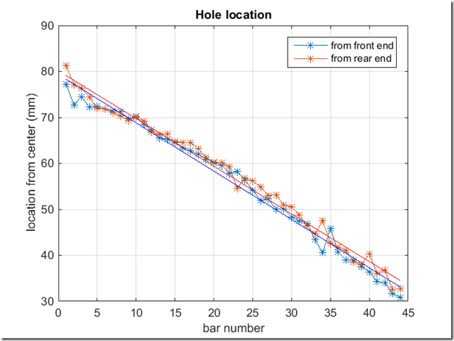
The symbols are the measured node locations from the front and rear ends of each bar (we define “front” to be the bar ends that face the player). There is clearly a gentle deviation from linear, but it is modest, so I chose to ignore it. Doing otherwise would force me to mount the suspension posts along a curve, which would obviously complicate construction.
Of course, the holes must be drilled at an angle relative to the bars. To figure out the hole angles, I wrote a little code to plot the locations (as if you were looking down on the instrument). I left 1/4 inch spacing between the bars, which might be a little tight for mounting posts, but I can space them a bit more later if needed (this, of course, affects the angle slightly, but the change is negligible). The following figure shows the output of this code.
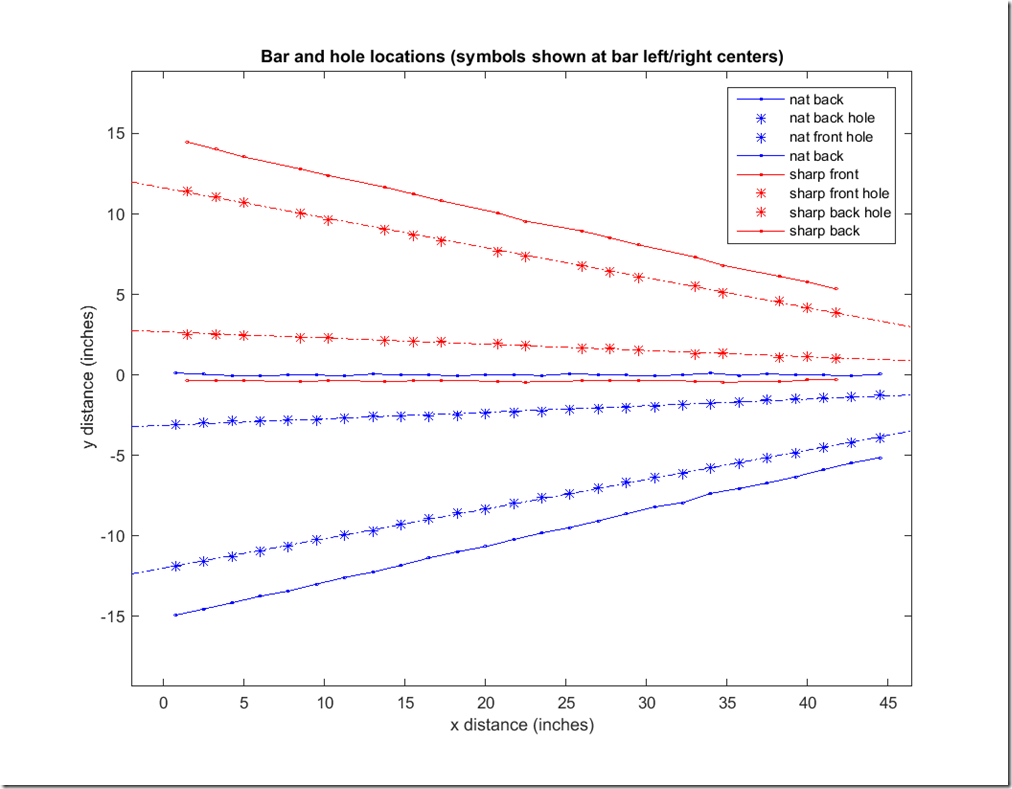
There is a lot going in this figure, so let me explain. The plot basically shows the location of the bars’ ends and posts in physical space. The blue solid lines show the locations of the natural bar ends. The red lines give the same info, but for the sharp bars (also called the accidentals). As you can see, the front edge of the sharp bars overlaps the back end of the natural bars. This is allowed, as the rear bars are elevated. In general, it is desirable to have the accidental bars as far forward as possible to minimize the reach needed by the player. The asterisks show the measured node locations for each bar, and the dashed line is the best linear fit through the node locations. If you look carefully, you will note that the solid lines (the bar end locations) are a bit wiggly. This is because I shifted each bar for and aft (actually Matlab did it) to split the difference between the best-fit line and the node locations. I did this to minimize the distance between the linear fit and the true node locations. Aesthetically, this is somewhat undesirable (i.e., the bars ends are not perfectly lined up,) but results in more bar sustain, since the damping due to the mounting string is minimized.
The hole angles that I computed from Matlab were
Natural front hole angle (deg): 10.4
Natural back hole angle (deg): 2.3
Sharp front hole angle (deg): -2.2
Sharp back hole angle (deg): -10.5
Jack and I started marking all of the computed node offsets on each bar, but this got pretty tedious. In the end, we laid them out carefully on a piece of craft paper that had markings for the horizontal locations and then empirically adjusted the bars to get the best fit to a straight line. Here are a bunch of photos showing the layout and alignment to the penciled node locations:
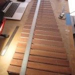
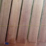
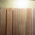

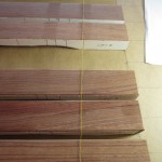
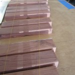
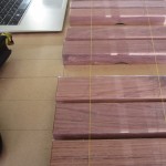
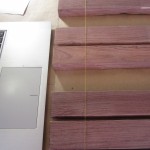

The yellow thread was stretched between two posts to establish a perfectly straight line. As noted above, we visually scooted each bar to try to minimize the distance between the yellow thread and the penciled node marks. When we got them sufficiently aligned, we laid down a 4 foot straightedge aligned with the thread and marked the compromise hole locations on each bar.
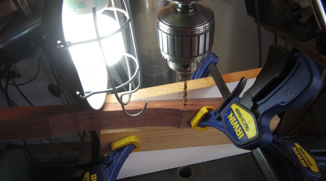
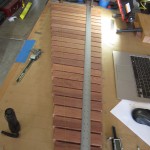
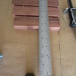
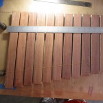
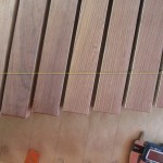
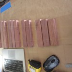
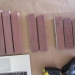
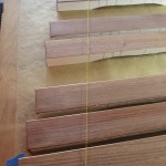
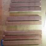
Finally, at the top of the page is a picture of the drilling operation. We faced a 90 degree cast iron angle block with a piece of 3/4 inch melamine that had lines for the 2.2 deg and 10.5 deg marks drawn on it. We clamped on a stop block aligned with the marks to keep the bar from sliding down the melamine as the holes were drilled. For the 10.5 degree holes, we used a center drill to start the holes to avoid bit wander and then finished the holes with a 3/16 inch drill bit. Here is a photo of all of the bars with the drilled holes:
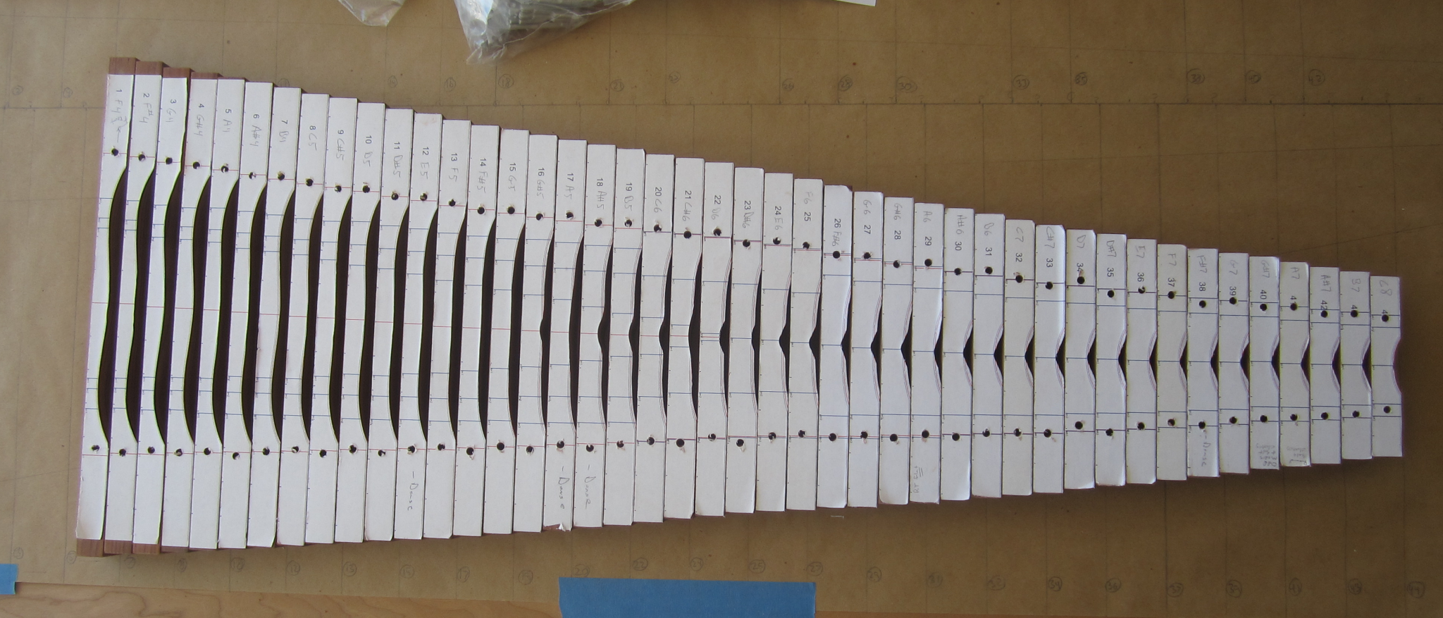
The red lines near the holes of each bar correspond to the computed node locations. The agreement is between these computed locations and the drilled hole locations is generally quite good.
In the next post, we will move forward with the fine tuning after which we will have almost completely finished bars!
Hi, I am making a xylophone at school and would like to know if it was possible to have the Mathlab code to locate the holes in the xylophone bars.
Thank you for your help.
Hi Marion – As noted in a previous reply to comments, the code to compute the holes does not exist, and would not be accurate for the short bars anyway, since they violate assumptions in the beam theory (i.e., the length to width ratio is too small). I used the salt method, which is fun and accurate.
Good luck with your project. Please send photos as it progresses.
Thanks, Rich