I wasn’t done torturing my maple test bar. As previously mentioned, xylophone bars are suspended by strings that pass through holes drilled at the nodal locations. From a practical standpoint, I needed to assess whether drilling the holes would affect the modes. If so, I would have to first “rough tune” the bar, drill the holes, and then finish tuning the bar.
Finding the Nodal Locations With the “Salt Method”
A few sites online, including the La Favre site, suggested using the “salt method” to determining the nodal locations. This technique has you sprinkle salt on the bar in a random pattern, and then repeatedly strike the bar. Because the bar vibrates minimally at the nodal locations, the salt slowly migrates to the nodes. It’s really cool and sort of magical to watch. I didn’t take photos of the salt method applied to my maple bar, but here are some before-and-after photos of the salt migration for one of the rosewood bars.
The salt makes pretty clean little lines, clearly marking the location of the nodes. (As a brief aside, the lines are rarely perpendicular to the long axis of the bar – they are almost always angled. This is just due to the wood grain, which the MEs would refer to as “the non-isotropic nature of the material.”)
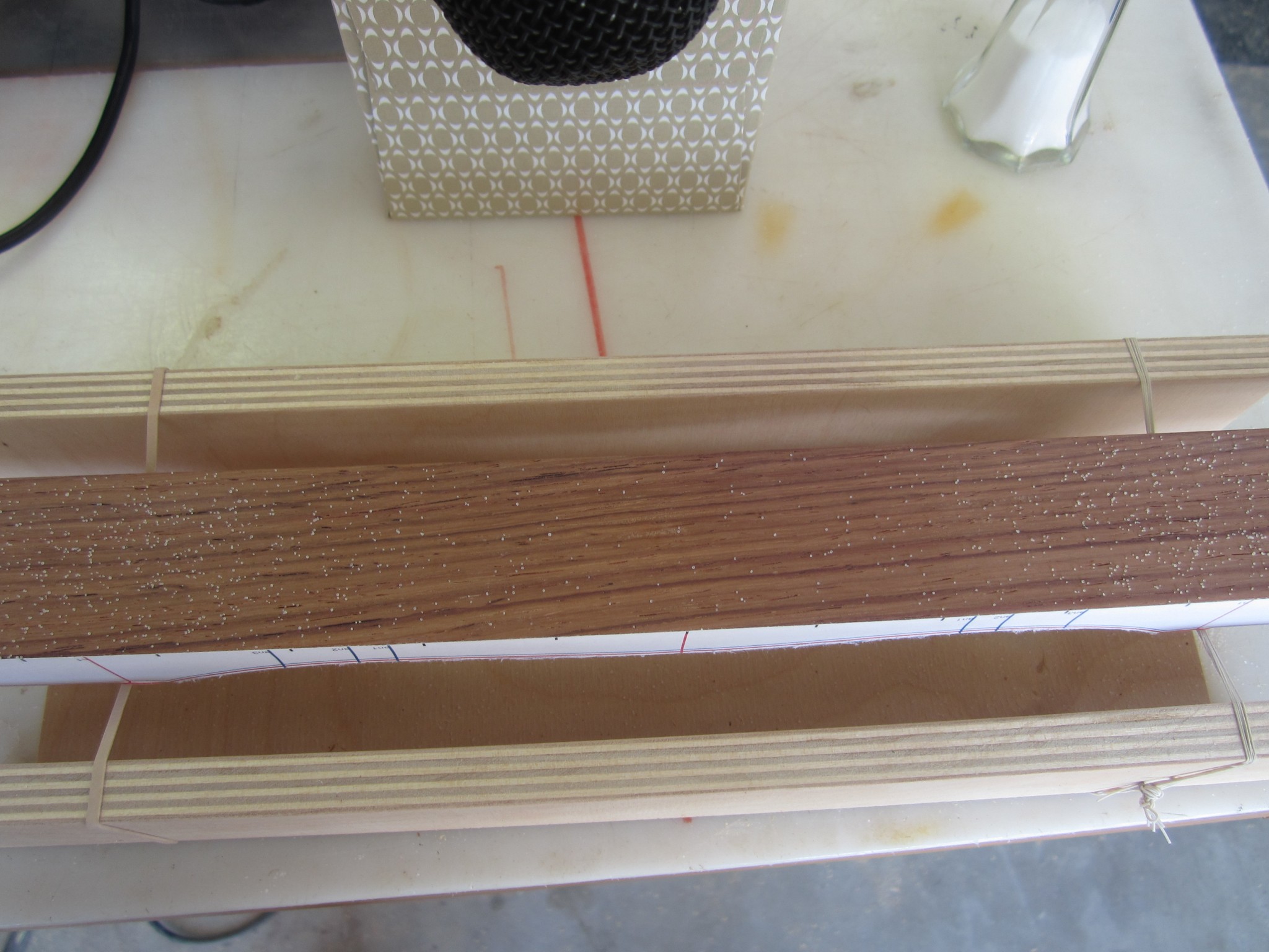
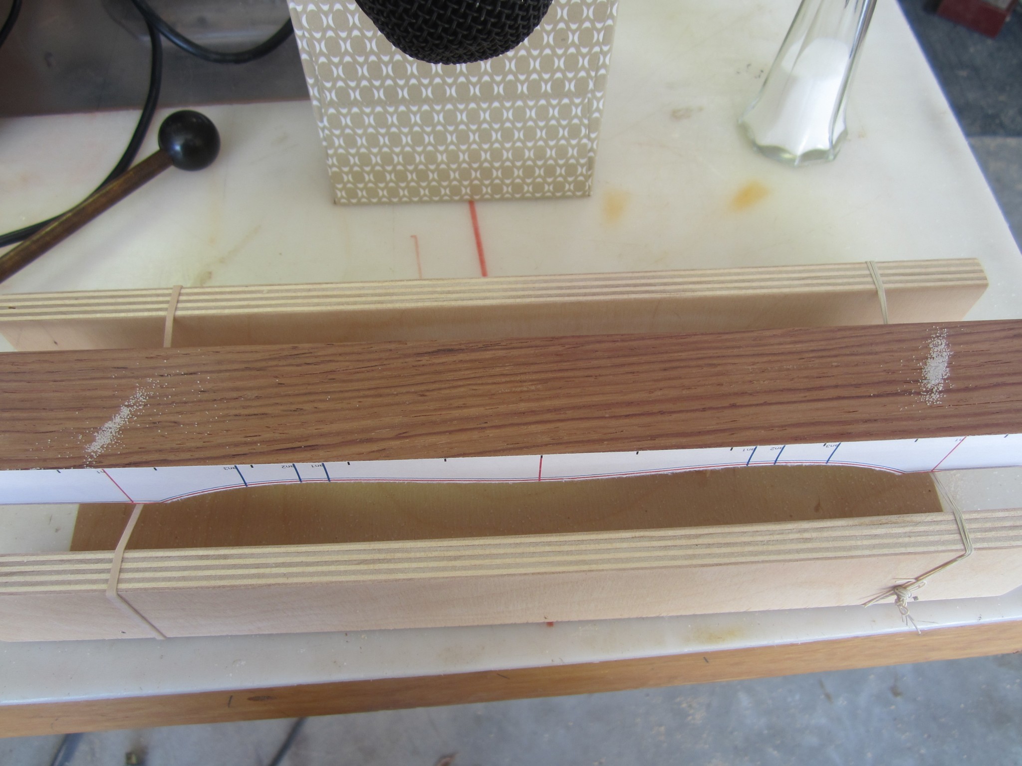
Jack and I used the salt method to determine the locations of the nodes for our maple bar and drew lines with a pencil though the middle of the salt lines. However, the results were surprising – the nodal locations determined by the salt method did not align with the “n1” locations predicted by the the tuning curves (refer back to the figure containing the bar template).
Recall that my n1 marks correspond to the location where the tuning curve crossed zero; that is, removing wood here has no effect on the modal frequency. I speculated that these zero-crossing points might be coincident with the nodal locations, reasoning that since wood removed here does not affect the fundamental, it might also identify the nodal locations. However, as noted above, that was not the case. Here is a photo with annotations showing the difference between the predicted and measured nodal locations.
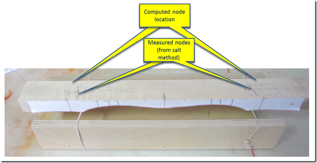
The measured and computed node locations differed by about 1 cm. This disturbed me, because up until this point, all of the computer predictions had been spot on.
Making a Friend
So I went back to literature to see if I could find some clues. The Zhao paper that provided the original version of the beam software referred to a function called Drilled_Hole_Predictions.m. A comment in the code indicated that this function would calculate the necessary location of the holes. However, the source code for this particular function was excluded from the appendix of the Zhao paper. As I have previously mentioned, comments in the source code indicate that it was derived by code written by Dr. Rodney Entwistle of Curtin University of Technology in Perth, Australia.
So I sent Dr. Entwistle a note explaining the mission that Jack and I were on and asked if I might trouble him to provide the missing function. To my great surprise, Dr Entwistle replied quickly and was very interested in our project! Being an amateur woodworker himself, and a father to four boys, I think he identified with the challenge that Jack and I had undertaken. So “Rod” and I begin a long series of correspondence that provided not only the node location function, but countless invaluable insights and pointers. Most importantly, his enthusiasm and continual encouragement kept me motivated to finish this project, even when it got tedius. Indeed, much of the material in this blog is the result of insights provided by Rod. I feel very lucky indeed to have found not just an expert who was willing to aid our pursuit, but a like-minded engineer that was a “geeked out” as I was by this engineering journey!
Back to the node location mystery. Rod pointed out that the nodal locations are not coincident with the zero-crossing computed by the tuning curves, and provided a function that computes the deflected shape of a beam. This code essentially computes the magnitude of deflection as a function of the longitudinal beam location. I used Rod’s code to compute the deflected shape curve for my maple bar, as shown in the following figure.
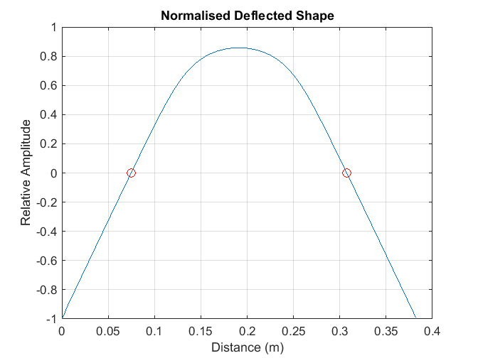
The two red circles mark the zero crossings – the point where the transverse beam deflection is zero (for the central axis of the bar). Relative to the longitudinal bar center, this gives the nodal locations at +/-116.3 mm. The locations that I measured, base on the salt method, were at +/- 115 mm, yielding a difference of only about 1 mm! This remarkable agreement indicated that I was indeed on the right track and ready to move forward with my rosewood bars all thanks to Rod, his code, and his excellent guidance!
One More Gift From “The Giving Bar”
With renewed confidence afforded by the excellent correlation between the predicted and measured nodal locations, I was ready to proceed with a final experiment on my maple bar. At the top of this post, I discussed needing to assess the sensitivity of the bar frequencies to drilling the suspension holes. After the lengthy side trip into computing and measuring nodal locations, we were finally ready to perform that experiment.
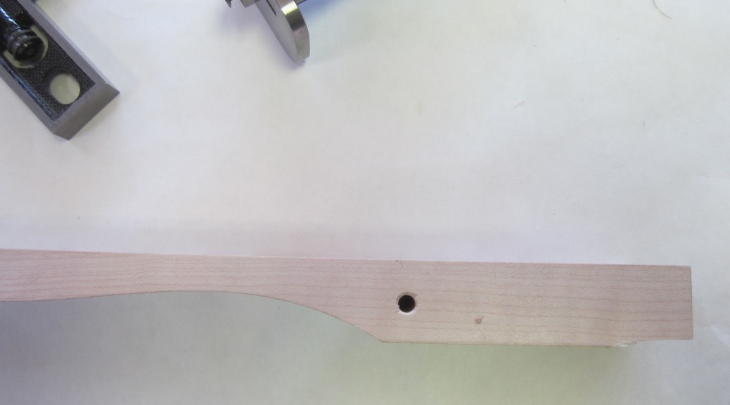
I spectrally measured my bar before and after drilling the holes so that I could assess whether it had an effect on the modes. I made the holes 3/16 in diameter, which was based on the cord that I chose to suspend the bars. (You’ll hear more about the mechanics of the woodworking, the cord, and other material choices later). The top of this post contains a photo of the hole, so you can get a sense of its location and scale.
Here are the results of the spectral measurements just before, and after, the holes were drilled.
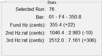
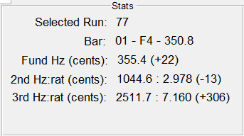
The spectral analysis shows that the fundamental frequency did not change at all, but the second partial got a bit flatter. This finding suggests that I could mostly ignore the hole effects when making my rosewood bars. However, just to be safe, I ended up cutting and tuning all of the rosewood bars a little sharp, then drilling the holes, and then performing the final tuning.
Done With Math
It seems like I have said this before, but at this point I felt like I was ready to actually begin making the rosewood bars. The maple bar experience was invaluable to bolstering my intuition and understanding of the fidelity of the math and the tuning process. I apologize if all of the previous discussion of Timoshenko beam theory, bending modes, and spectral analysis gave you a headache. If you are still with me, the rest of the posts will be your reward! We are about to build a xylophone!
Rich
I enjoyed reading your blog. I am a hobbie woodworker and my 8 year old son is facinated by xylophones and marimbas. Would you be willing to share (or sell) your bar and resinator patterns and software?
Hey Stephen –
Glad you enjoyed the site. I can’t believe you found it, since I haven’t really posted it anywhere yet. I am trying to get it more complete, and then my plan was to try to get a bit more exposure. I’d be interested in how you found it. Was it just a search engine?
Yes, I can share the bar patterns. I intended to post them on the site, but I just haven’t gotten there yet. I was thinking that I would just post full-scale PDF files. This evening, I am working on a post where I will include each of the bar dimensions. Between those and the PDFs, you should be good to go.
The software that I wrote is problematic as it is technically owned by my employer. Even though it is completely unrelated to my work, they lay claim to any software I write. I am trying to find out the details to see if I can get an exception. Please stand by on that.
Thanks for checking in – it’s nice to know that there is at least one other guy out there who digs this stuff!
I found your blog through a featured article in an email from Speedy Metals. I am mostly an electronics engineer, but lately I have become interested in metalworking. So I posted a link to your blog on one of my favorite forums, http://bbs.homeshopmachinist.net/forums/3-General. I found the discussion of the technology of the xylophone and tuning to be quite interesting. I’m not really a musician, but I enjoy playing guitar. Thanks for the fascinating story of your project.
Hi Paul – Glad you enjoyed the blog. This project was the perfect blend of art-meets-science-meets-engineering. Both my son and I learned a ton. Thanks for posting the link to homeshopmachinest. I’d like to get this info out to folks who can use it. I spent some time perusing, and that forum looks really interesting. I would love to grow my shop to include machine tools to do metal work; may dad was a machinist and I suppose I have it in my blood. Now I just need to find the space and dollars! No shortage of project ideas…
Best, Rich
Would Dr. Rodney Entwistle mind if you post the function that computes the deflected shape of a beam? It would be great to see if we can replicate your results.
Hey Simon – I will reach out to Dr Entwistle and see if he minds sharing the code. Are you building an instrument or just messing with the math?
Rich
Hi Rich thanks for the reply. My Father and I are busy building a Marimba for fun (which is a strange project, since none of us can play the marimba). At the moment he is messing mostly with the wood, and I am messing mostly with the maths. So short answer, yes, we want to eventually build the whole instrument, and this blog is a tremendous help I should add :). B.t.w I think my father would love to chat with you, his email address is (remove the spaces and inject the “@” and “.” appropriately): d i r k s t m w e b c o z a
d i r k s t at m w e b dot c o dot z a
Sweet! Glad you are giving it a go Simon. I sent your dad an email, and am happy to help.
Best of luck!
Rich
Love the blog. Had a question with the hole drilling. When looking at your salt image, both salt lines are going in same direction ie. / /. But when drilling the holes, the holes due to how the bars are placed, should be more on the lines of / \ because of the frame. How did you drill them? Which end of the hole did you use? Angle? Just trying to understand. Thx for your hard work. Most informative site on building one I’ve seen to date.
Hey Allan –
Again, my reply is so latent, I imagined that you have worked this out some time ago. In any case, you are right that the frame dictates the ultimate location of the holes given that they are linear. My experience was that, while each bar had an optimal location (as discovered using the salt method), small deviations about this had negligible impact on the tonality. So prescribing straight lines through all of the bar holes was a compromise the that traded build complexity with audio quality.
Best, Rich