After cutting the tenons and mortises, Jack and I did the standard fine tuning on the mortises to get the parts to fit together accurately, but without a bunch of man-handling. It was important that the mortise and tenon fit wasn’t too tight, because four joints on each end must be fit simultaneously during the glue-up, and it is very hard to seat them all if they are tight. After a few dry fits, we were ready to mark and drill the holes in the rails that receive the saddle and corner posts.
Post Holes
Now I’m not going to lie – I can tend to be a bit anal-retentive when it comes to woodworking. Feeding this natural tendency was the fact that I knew that accurate placement of the posts was critical to avoid pinching the bars between the posts. To determine the hole locations, I created an Excel spreadsheet that computed the location of each post on each of the four rails. The computed locations were distances down the length of each rail, relative the shoulder of the tenon. The only problem is that I kept screwing this up- mostly due to the four unique angles and all of the offsets involved. I would compute the locations and then mark them on the rails with jack reading off the dimensions. But when we checked them, there would be some systematic error – like I hadn’t accounted for the offset due to the pin being in the center of the rail. I think we did this three times before we got it right – argh! Both Jack and I were frustrated by this tedious process (did I mention that there were 108 holes?!)
After we did it this way, I realized that there is a much simpler approach that I would use if I ever did this again. Let me explain…
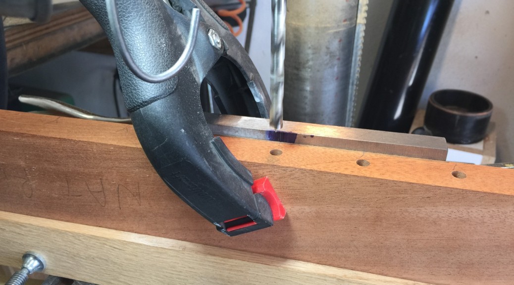
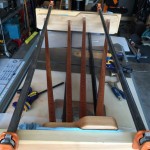
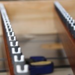
Computing the post locations relative to the left ID of the frame is straightforward (as opposed to distance down the rail). It is really just accounting for each bar and gap width. You do have to be a little careful with the offsets (i.e., edge-to-corner post, edge to first saddle pin, etc), but it is do-able with a little care. The tricky part is the angles involved and the fact that the index mark for the hole location has to be at the edge of the rail to make the drilling operation efficient. Let me clarify. Check out the photo at the top of this post. This is the setup on my drill press where we drilled the holes. Here is a zoom of the center of that photo:
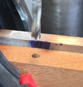
It may be hard to see in the photo, but there is a thin pencil mark on the edge of the Mahogany support rail that must be aligned with the scribed line on the steel angle jig behind the rail. The drilling process for each hole was basically to align the marks, apply a spring clamp to hold the board against the steel fence, and drill the hole. The spacing between the drill bit center and the steel fence was exactly 1/2 inch so that each hole would be precisely centered on the width of the board.
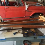
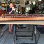
Here is a wider field of view photo of the drilling setup that may help:
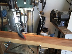
Because each rail is angled, there is a small offset between the desired X location of each hole and the mark at the edge of the board. Neglecting this, or getting the offset in the wrong direction is how I kept screwing up. Also, when making the marks on each rail, it is easy to mess up, since the distance down the rail is relative to the rail center line, not the edge. This is another way I screwed up. So here is a much easier approach that occurred to me after the fact.
Rather than trying to account for this angle-dependent offset, I would do the following:
- Dry fit the frame together
- Compute the location of each hole relative to the left or right ID of the frame end piece (i.e., in the X direction)
- Using the protractor head on a combination square, set the angle so head is against the rail and the blade is aligned with the frame end (so the blade is parallel to the Y axis)
- Slide the combo square down the rail to align the blade with the desired X location (e.g., using a tape measure that measures distances form the frame end ID) computed for a given hole.
- Draw a line on the top of the rail. This line will be slanted relative to the rail perpendicular.
Now you will have a slanted pencil mark at each post location. When aligning the mark on the drill press, you can not just line up the pencil mark with the index line on the steel angle block. If you do this, the hole will be offset a bit from the desired location due to the 1/2 inch thickness of the rail and the fact that the line is slanted. Rather, you will have to align the drill press index mark with the intersection point of the slanted line and the mid-point of the rail. A small right angle block could facilitate this, or you could draw an additional perpendicular line at each mark location.
Hopefully, my lesson will save you some pain, or perhaps you will have better luck with the calculations and getting all of the angles right – we finally did, but it was painful.
In the end, we got all of holes drilled, temporarily pushed all of the posts in the holes, and temporarily strung the bars with some string. Here is a photo of Jack with our assembled unit. It’s starting to look like a real instrument.
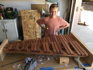
Jack couldn’t resist playing a little ditty. Here is a video of Jack playing his evolving xylophone for the very first time:
Shaping the Ends Pieces
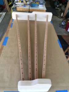
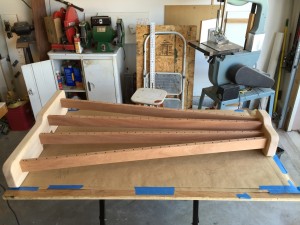
As shown on the photos of the previous posts, the frame ends at this point were just rectangular blocks, which look pretty clunky. As previously noted, we placed the mortises so that the top of the accidental bars were at the same elevation as the top of the rectangular frame ends. This was just an aesthetic decision. We thought it would look good to extend this idea to the natural bars too, which required the frame ends to “step down” to the elevation of the natural bar tops.
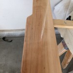
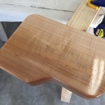
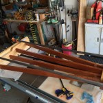
To avoid square, sharp corners, we also added little ramps that connected the two elevations and rounded all of the corners. Here is a photo of the nearly finished end pieces.
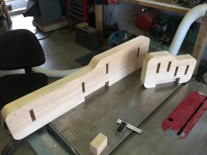
Notice that we also cut some big, rectangular mortises in the bottom of each end piece. This is to accept the two legs that we had yet to build. We’ll write more about the leg and foot construction in a later post.
To smooth the sharp corners, we routed a 1/4 round-over on all of the edges and dry-fit the whole thing together to take a look. Here is the result:
Applying Finish
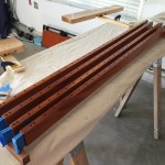
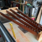
I chose lacquer for the frame finish. I like lacquer because it really brings out the depth in the wood but also because it drys quickly, so it is fast to build up a finish. We decided to finish the rails and end pieces prior to assembly for a few reasons. First, down at the right end of the instrument, the spacing is a little tight, so it is hard to spray finish in there. Second, there is inevitably glue squeeze out at the joints, and it is often hard to remove all of that glue prior to finishing. Any glue left behind will keep the wood from absorbing the finish which leaves unsightly “splotches.” So we put blue painters tape over the mortises and tenons and sprayed the parts with an HVLP gun. (I use a cheap $100 HVLP system from Rocker for the finish. For the price, this thing is actually pretty decent.) Here are a few photos:
It’s always fun to watch the grain pop on wood when lacquer is applied. The finish also brought out the beautiful color of the Mahogany.
After the finish dried, we glued and clamped the frame assembly. This was a bit “butt puckering” because it is a tricky to get the tenons simultaneously inserted in to the mortises before the glue dries, especially in arid New Mexico where the humidity is so low. Here are few photos of the glue-up:
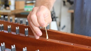
All that was left was to glue the posts into the rails. Each of the post holes was drilled with a brad-point bit to a fixed depth. This gave a nice square bottom to each hole that ensured that all of the pins would have the same elevation. The pins were snug in the hole, but over time may have wiggled out, or at least rotated, so I decided to drop a bit of glue in the bottom of each hole to lock the pin into place. I carefully inserted the glue into each hole using a toothpick and letting the glue drip in. This was slow going (did I mention that there are 108 holes,) so it took a while. Here is a photo:
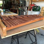
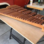
Here are a couple of photos of the completed frame:
And then came the moment of truth – Jack and I strung the xylophone bars on some brown para-cord, attached the springs, and hung the bars. Pretty cool – we now had a fully functional instrument, minus legs and resonator tubes. Here are some photos of the finished product:
It had been a long time coming, but we finally had an instrument! Jack and I moved this up to his bedroom at this point, so he could mess around with it, and to get it out of the garage so we could start working on the resonator tubes. More on that in the next post.
We’ll leave you with Jack playing a little song in his bedroom.
