Making the tubes wasn’t a big deal – really just cutting them to length and finishing the aluminum so it looked nice. However, mounting them and making the stoppers was some work and is probably worth sharing for anyone interested in building an instrument.
Making the Tubes
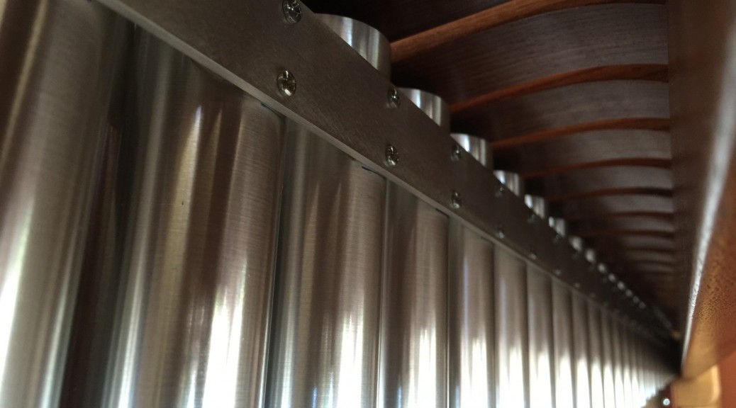
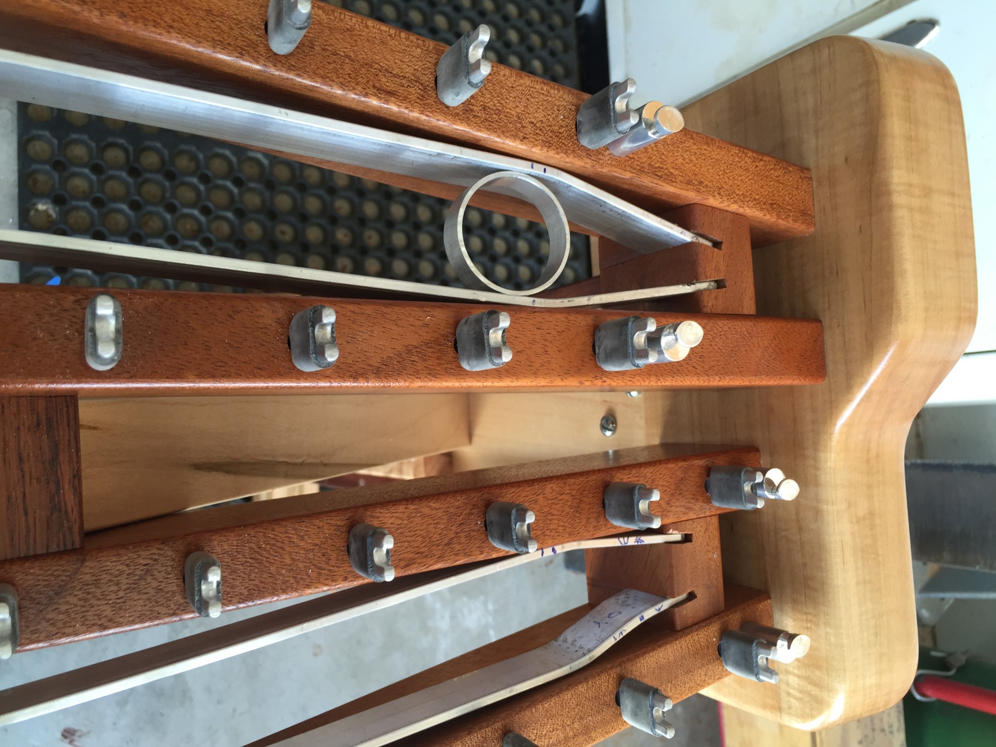
In discussing the construction of the xylophone tubes, perhaps it is most clear to start with an overview picture. The photo below shows the tubes mounted to aluminum rails that are in turn mounted to wooden blocks attached to the frame ends.

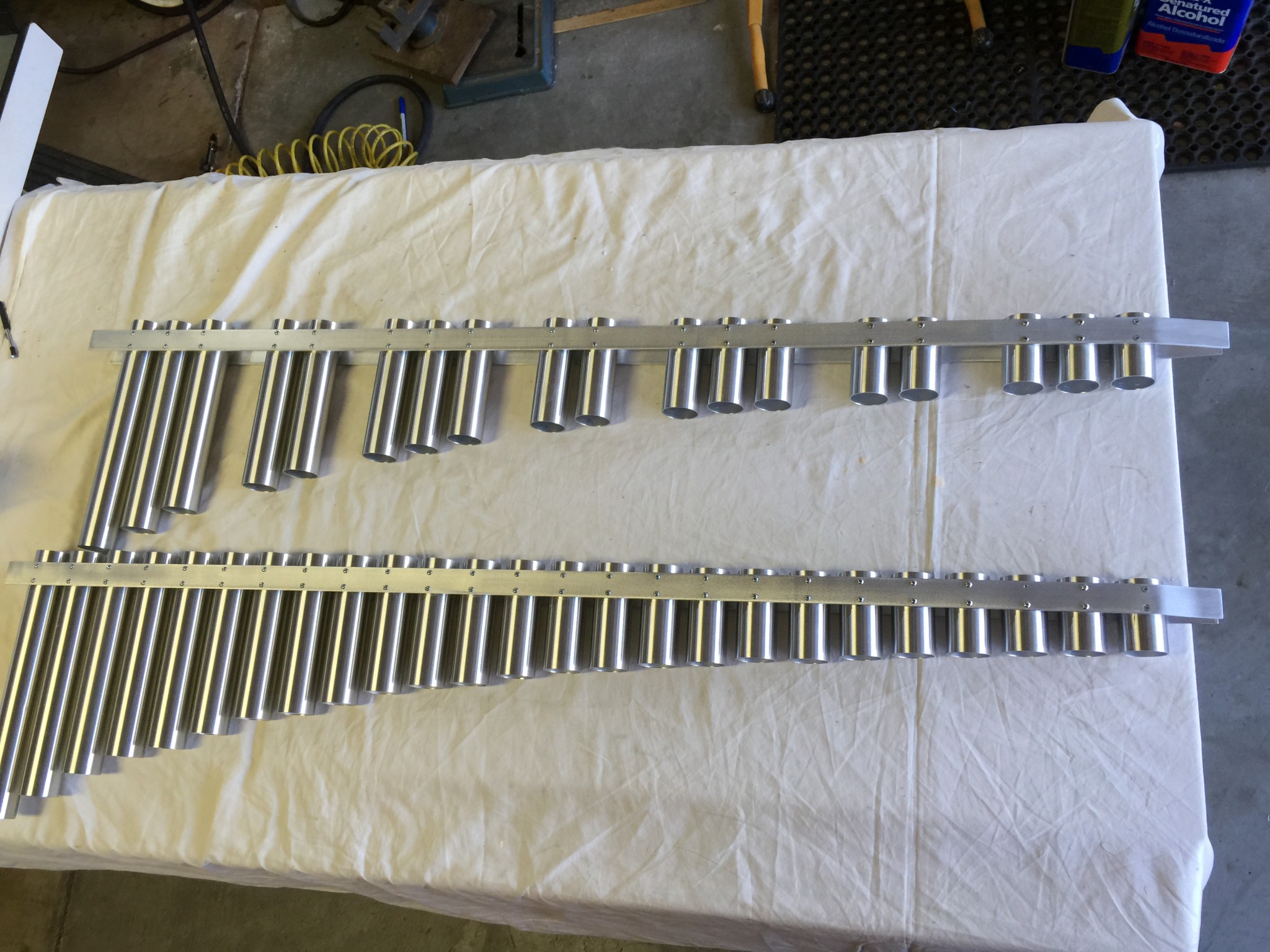
The xylophone tube assemblies are quite rigid after the tubes are attached to the 1/8 x 1 inch aluminum rails. Here is a photo of the assemblies:
As shown in the top photo, the assemblies fit snugly in the slot cut into the mounting blocks shown in the top photo.
The construction of the tubes themselves was pretty straightforward, but there were a few nuggets along the way that might help someone building their own instrument, so I will describe the high points.
As noted in a previous post, I bought the tubes from Speedy Metals (again, I love this place – great prices and selection and cheap shipping) in four foot lengths of 1/16″ wall aluminum . As with the bars, I used the CutList Plus software to optimally allocate the 43 tubes into the four foot stock pieces. As noted in the previous post, I calculated the theoretical length of each tube and added two inches to allow for the stopper. This was overly conservative, because the stopper was only 3/4 inch thick, but my worst nightmare was cutting all of the tubes too short!
The tubes were cut on my sliding compound miter saw using a non-ferrous metal blade. I typically shy away from cutting metal on my woodworking tools, but I was amazed at how well it cut and how perfect the edge was. Here’s are a few photos of the cutting setup and some of the cut tubes:
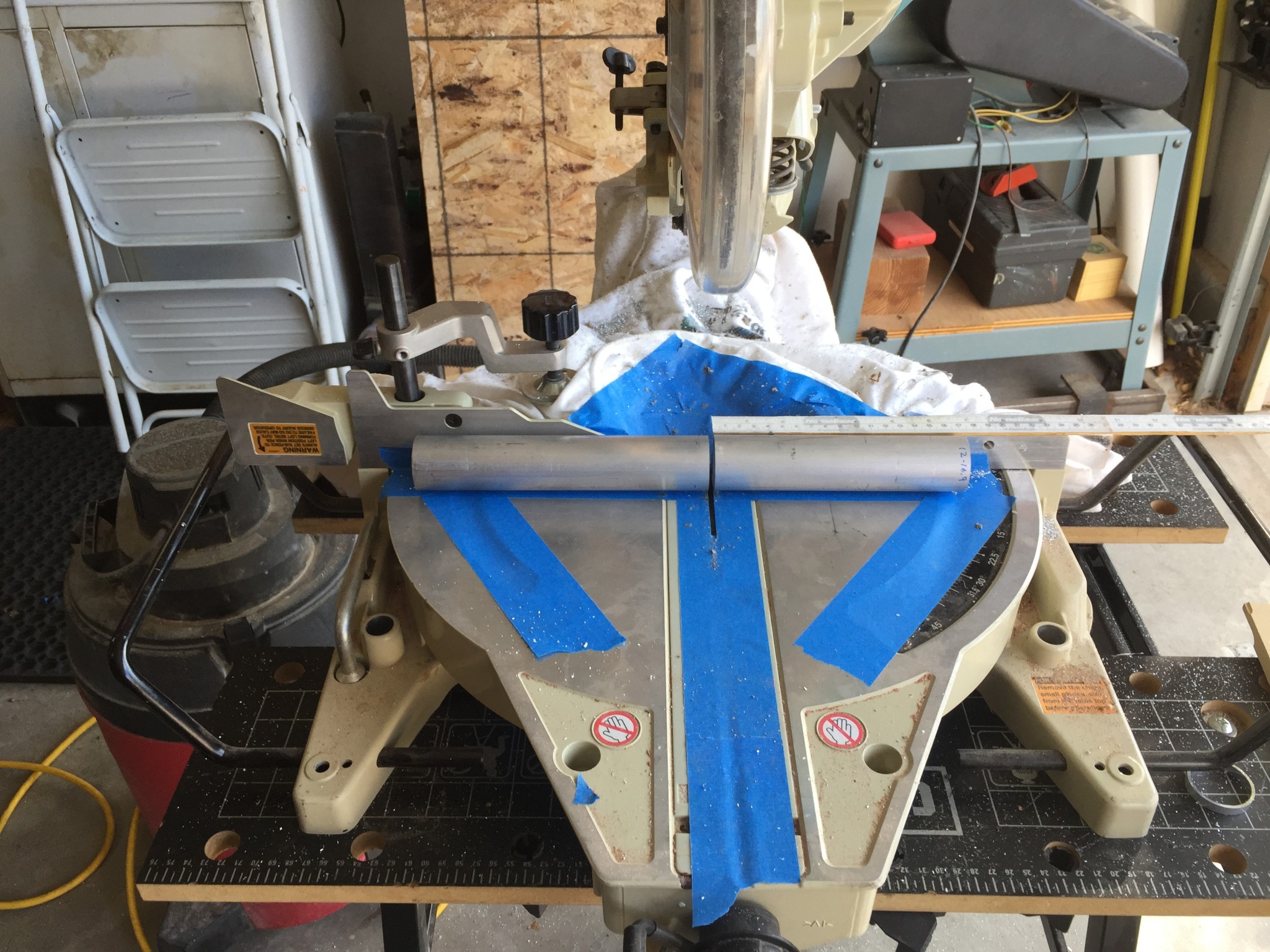
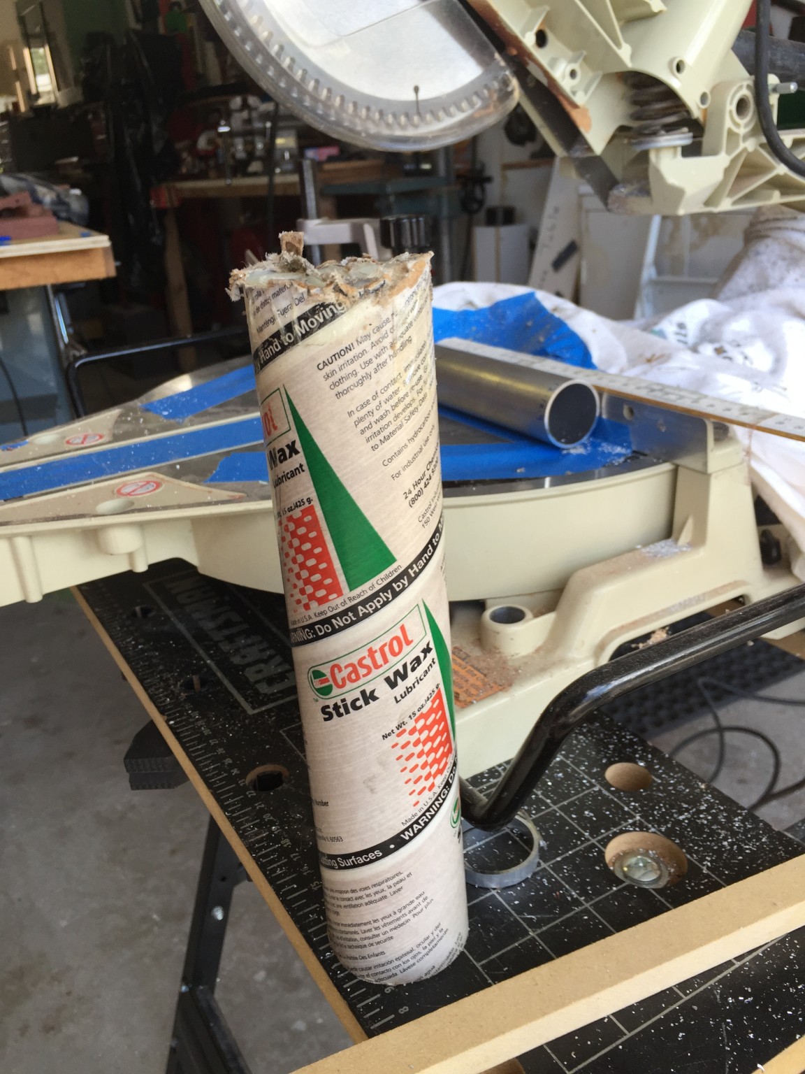
Note the tube of wax next to the saw. I used that to lube the blade before the cuts. Not sure if it was required, but aluminum can gall when it is cut, so it seemed like a simple precaution.
The surface finish of the stock tubes left a little to be desired, so I decided to “brush” the aluminum. To do so, I built a mandrel to hold the tube so that it could be chucked into a hand held drill. Below is picture of the mandrel.
To make this, I cut a wood disk and drilled and tapped a hole in the center, and then inserted a threaded rod. The disk had a slot cut partway through it that could be spread somewhat by driving two wood screws into it. To attach the mandrel to the tube I simply inserted the wood disk into the end of the tube and then tightened the two wood screws. This spread the slot to make the wood disk clamp to the interior of the tube.
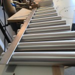
With the mandrel inserted, brushing the aluminum was easy. I just spun the tube with a hand drill while sanding the tube with 120 grit sandpaper. It was actually kind of fun to see the dull aluminum brighten up as it was sanded. After sanding, I blew the dust of the tube and wiped it with alcohol to remove the oil, wax and dirt from the tube. Then, while slowly spinning the tube with the drill, I sprayed gloss lacquer on each tube. Some sort of varnish is required to ensure that the tubes don’t oxidize. I used lacquer because I had it on hand and it dries quickly, but there are products specifically made to protect aluminum. I was able to carefully remove the mandrel from the tube even prior to the finish drying so that I could move on to the next tube (did I mention that there were 43 of them?!) Anyway, here is a shot of some brushed and lacquered tubes:
Making the Assemblies
With the tubes completed, I turned my attention to making the aluminum tube support rails. Here’s where I probably overkilled things. As I stated in the previous post, the short tubes add little or no sound amplification. However, at this point I didn’t appreciate that fact. So I was hell bent on getting tubes on as many of the short bars as possible. The problem was that the Mahogany frame rails get really close together at the right end of the instrument. This didn’t leave much room to fit the tubes in. Here is a photo of the aluminum support rails at the skinny end of the instrument:
As you can see, I had to carefully bend the rails to get them to fit correctly. I’m not gonna lie – getting those rails bent just perfectly was a bitch! Once they were bent, I was able to mark the angled slots on the wood support blocks, but getting the bends right was tough. So if anyone out there is still listening, here is the lesson: don’t bother making or mounting the short tubes. They don’t change the sound, and its also not an aesthetic consideration because you cannot even see the short tubes since they are mostly obscured by the Mahogany rails. If I had to do this over again, I would skip the shortest tubes and just use straight rails, thus avoiding the bends and all of the tight clearance issues. Live n learn…
Attaching the Tubes to the Rails
Now, I racked my brain on how to mount the tubes to the rails. There are two challenges. First, attaching a round tube to a straight rail is tricky, since the tubes want to roll and slide along. Originally, I was thinking of making a big jig to hold everything in place, but that was going to be a lot of work. Second, I wanted a constant standoff between each tube end and the bottom of its corresponding bar to maximize the tube/bar resonant coupling. Because the undercuts on the bars are all different thicknesses, this means to tops of the tubes are not in a plane – some are higher and some are lower. It is possible to measure the standoff for each tube and transfer that to the jig, but I was sure I would screw up all of that bookkeeping.
Ultimately, I converged to an approach where I glued all of the tubes to the rails and then later added screws to make the bond stronger. Let me elaborate a bit.
As the photos above show, the tube rails hang in slots that are cut in wood blocks attached to the frame. With the rails in place, and the xylophone bars strung, it is possible to slide each tube between the rails, from the bottom, and set both the position on the rail and the height of the tube. To set the height, I cut a ring from a scrap piece of tube that was ~1/4 inch tall. Then, I would sit the ring on top of the tube, like a spacer, and raise the tube until the spacer just touched the bar. At this point I would slide the tube left and right until it was aligned with the bar. Now, without moving the tube, I would mark small index marks on the tube and rail so that it could be re-positioned later. This process was repeated until I had marks for all of the tubes.
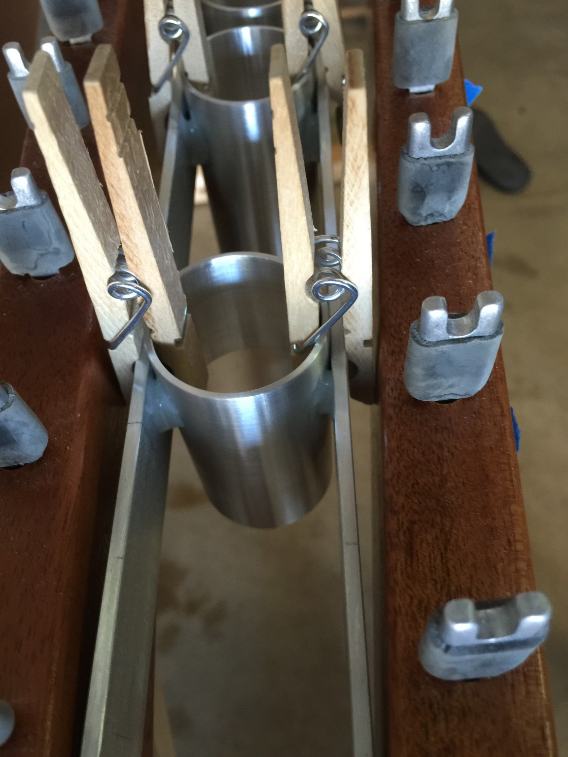
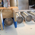
At this point, I was able to remove the xylophone bars from the frame and start to mount the tubes. Friction between the rails and the tubes was insufficient to hold the tubes in place, but I found that I could use wooden clothes pins to hold the tubes in place. (Remember clothespins? I had to buy them on Amazon because it had been years since we’ve had any in the house). Here is a photo of some of the tubes in place:

That’s Jack helping in the background.
Once the tubes were in place, I just needed to add epoxy to temporarily hold them. I mixed up some West Systems epoxy and added a silica thickening medium to make the glue more viscous so that it didn’t drip. Then, using a toothpick, I very carefully made a little epoxy gusset on each of the four crevices around the tube. This was a little tricky, but all of those years as a kid playing the board game Operation paid off! Here is a picture of the glued tube:
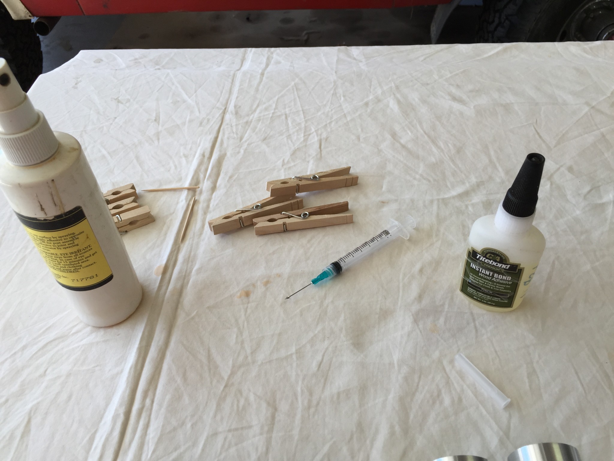
For a few of the last tubes, I used a syringe to inject the glue into the tight crevices. The epoxy was too thick to pass through the syringe, so I used superglue instead. This was much easier and cleaner, and I was able to get the glue deep into the crevice so that the glue didn’t run much. I also sprayed the glue with accelerator to further avoid runs. Wish I had thought of that first. Here is a picture of the syringe and glue I used:
In any case, the glue is just temporary. While the bond is actually stronger than I expected (I made a test piece and broke it apart,) I wouldn’t want to count on it for the life of the instrument. So once all the tubes were glued in and set, I was able to gently pull the whole assembly out for the next step – adding mechanical fasteners to each tube.
I found some 4-40 screws that were 3/16 long so that the end of the screw was just flush with the inside of the tube. Here is a picture of the completed assembly, so you can see what I am talking about:

Drilling and tapping the screws was tedious, but I made a jig to help.
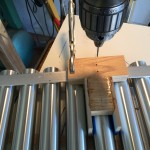
The jig was just a little T-shape of wood with wings that straddled each bar. It had two holes in it to guide the drill for each pair of holes. This made drilling the holes pretty speedy even though there were a lot of them. The drill I used was for the 4-40 threads. After these holes were drilled, I put in a body drill and just drilled 1/8th of an inch, which was the thickness of the rail. This ensured that the screws pulled up tight to the tube.
I tapped each tube by using a tap, a battery powered drill and a bit of lubricant. Tapping 1/16th inch aluminum is pretty easy, but you do have to be very careful not to break the tiny tap. I did break one during the operation, but had some spares on hand.
Making the Stoppers
I gave a lot of thought to how to build the stoppers. Again, there are a lot, so I was trying to find the most efficient way to bang these out. The stoppers had to fit snugly in the tube and have some means of locking them. I figured I could use the same screw-spreading-split idea that I had used for the mandrel, but I still needed to make 43 disks. I considered a hole saw (couldn’t find the right size,) 3D printing (I don’t own a printer…yet,) slicing a dowel (couldn’t find a vendor to make a custom size dowel,) turning a dowel (I suck at wood turning,) casting the plugs using urethane (slow and expensive,) and a few other ideas. In the end, I made the wood disks using my band saw and router. Let me explain.
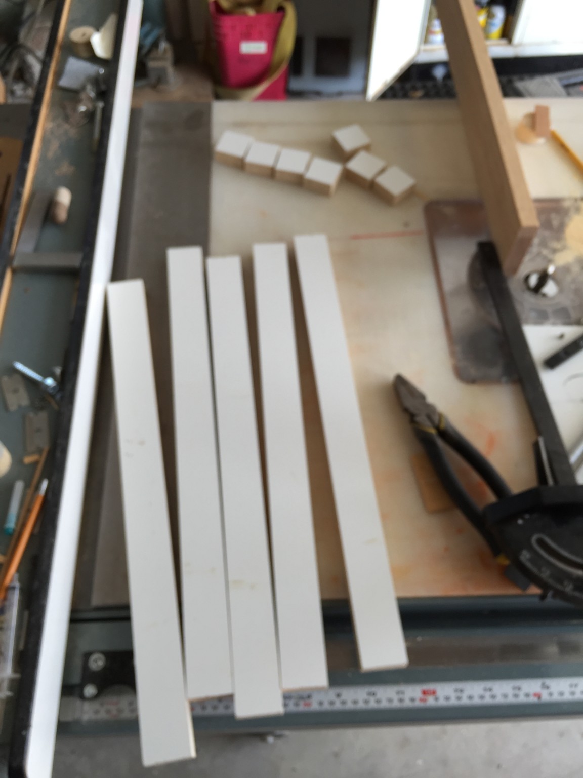
I started by cutting 43 squares of 3/4 melamine. Melamine seemed good because it has a nice hard and flat surface to reflect the sound.
Next, I set up a quick jig on the drill press to drill a shallow 1/4 inch hole directly in the center of each square.
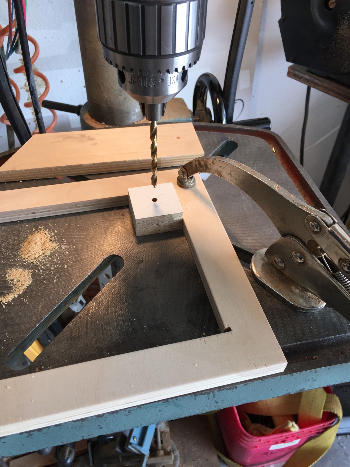
The plug will be flipped over and this hole will slip onto a 1/4 inch steel pin protruding from a sliding jig. The following photo might make this more clear.

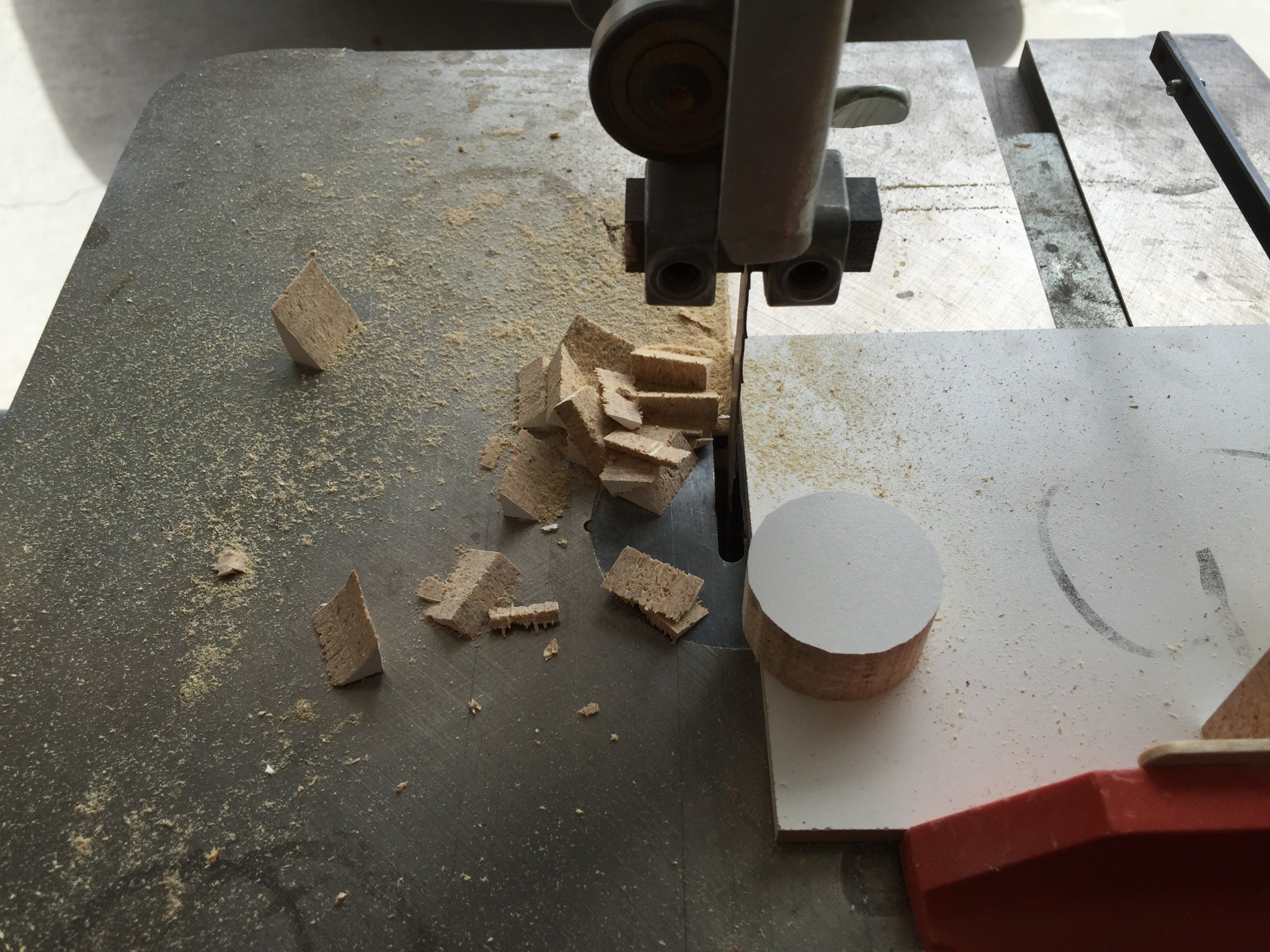
In this photo the wood disk has been inserted on the pin (not shown, because it is hidden under the disk). The jig then is slid up to a stop such that the block can be rotated to cut a rough oversized disk, as shown in the following photo.
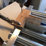
Once the disks are roughly sized, I moved the jig over to the router table. This operation was similar – slowly slide the jig up to a stop and then rotate the disk into the router bit to trim the edge. Here is a picture of that operation:

This was pretty dusty, hence the dust collection. This all worked pretty well, and was pretty speedy, but was a little nerve-racking as my fingers were pretty close to that big-ole router bit. But alas, I finished with all of my digits intact.
The next step was to drill the hole for the “spreader screw.” So I went back to the drill press as shown in the following pic.

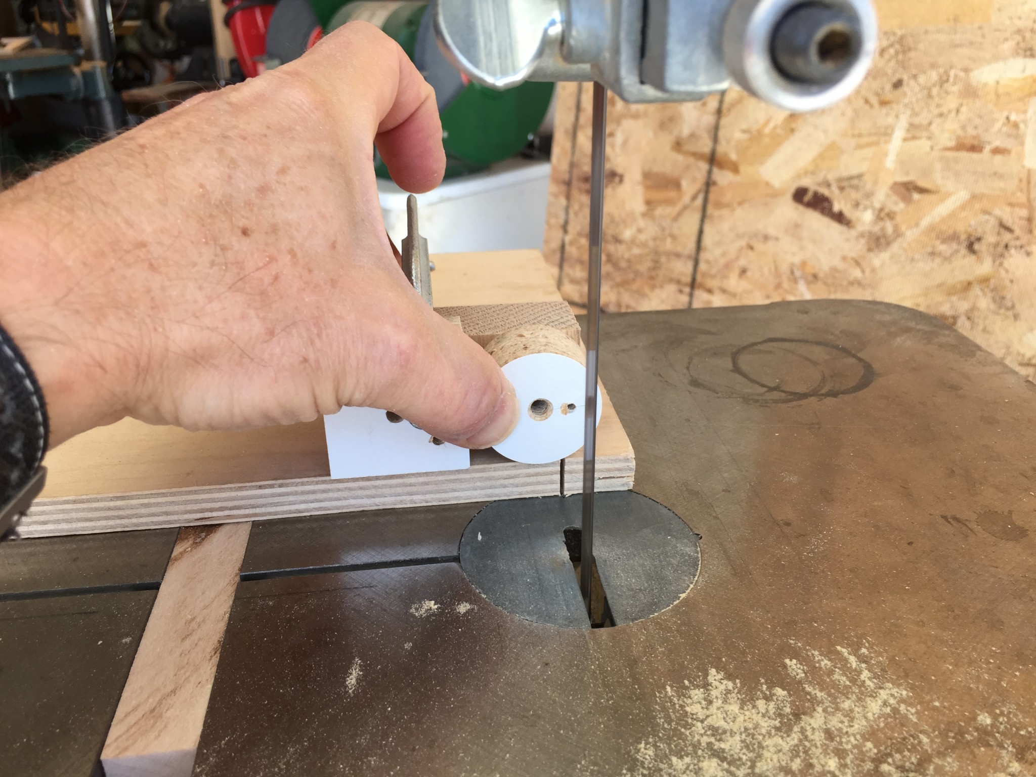
I used a tapered drill so that the screw started more easily. Finally, I cut the slot on the band saw as shown in the following photo.
When I was all done, I had a bunch of stoppers that looked like these:
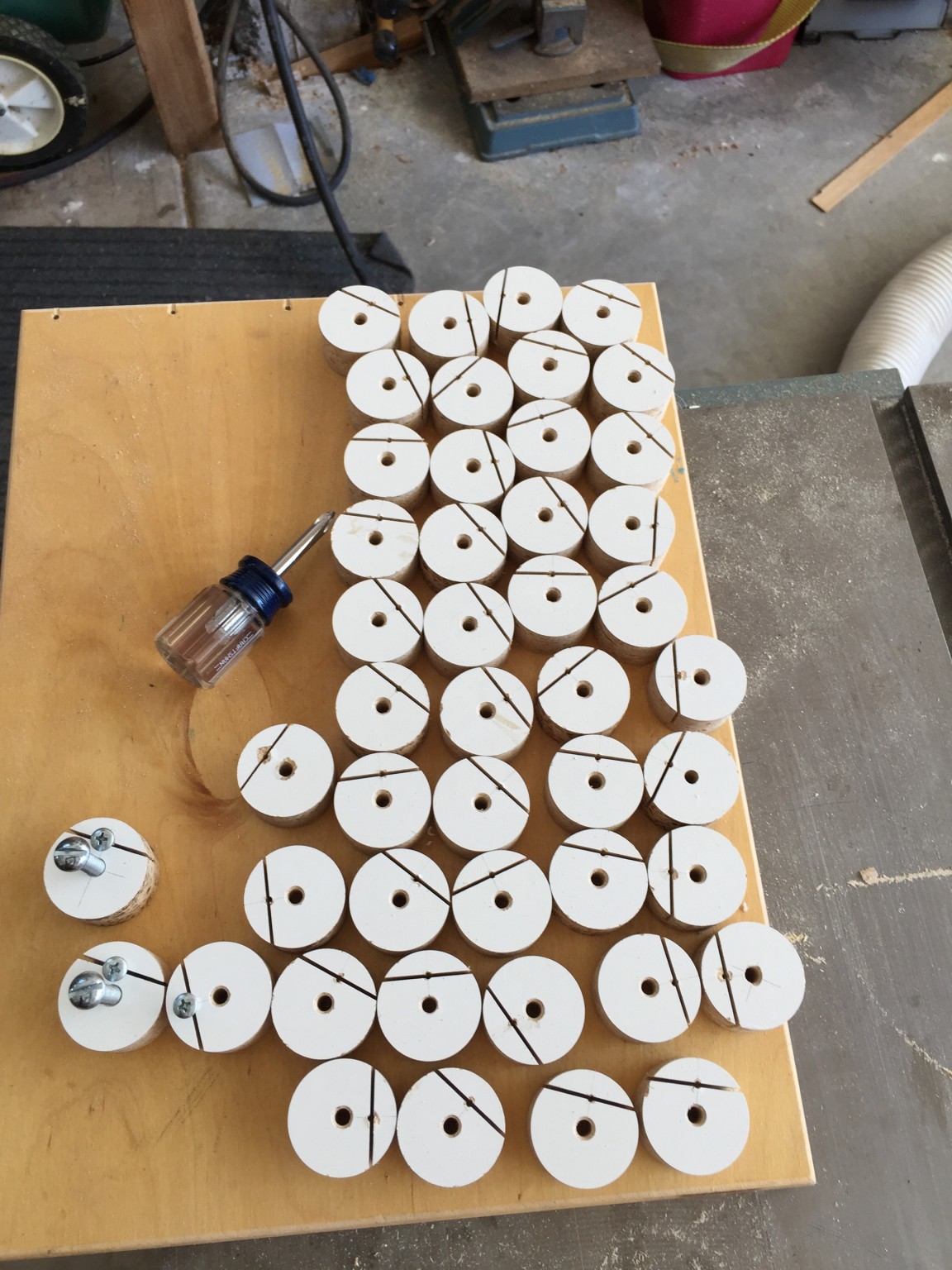
I forgot to mention it, but I also tapped a 1/4-20 hole in the center. This is to insert a long machine screw that was used as a temporary handle to adjust the stopper up and down during tuning. This screw along with the spreader screw is shown in the stoppers at the lower left.
In the end, the stoppers worked pretty well. Here is a picture of the a few of the tubes with the stoppers installed.
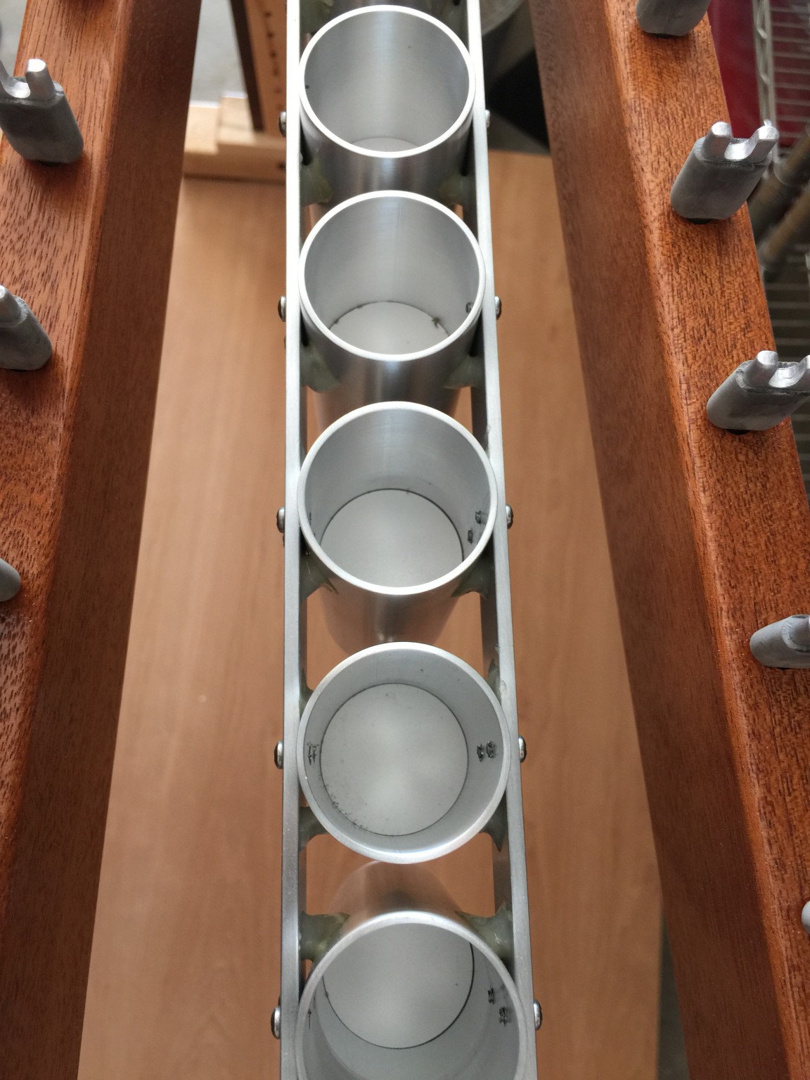
Not sure if you can see clearly in the photo, but the stopper fit is pretty tight.
The Final Post
Our little xylo-adventure has just about come to an end. In the final post, I will describe making the legs. This is mostly just straightforward woodworking, but I will discuss a few design considerations that may be if interest.